Phone Case
Background
- Protective cases for mobile phones present an extremely lucrative market opportunity, valued at over $21.36 billion in 2019.
- This market share is expected to grow even larger at a rate of 6.5% annually until 2028.
- As smartphones continue to evolve in their capabilities and become a more integral part of daily life, more and more consumers seek out phone cases to provide protection for their phones.
- Cases help phones withstand daily wear and tear, provide protection from damage due to drops, and serve as a pleasing visual aesthetic.
CAD
Design
Rationale
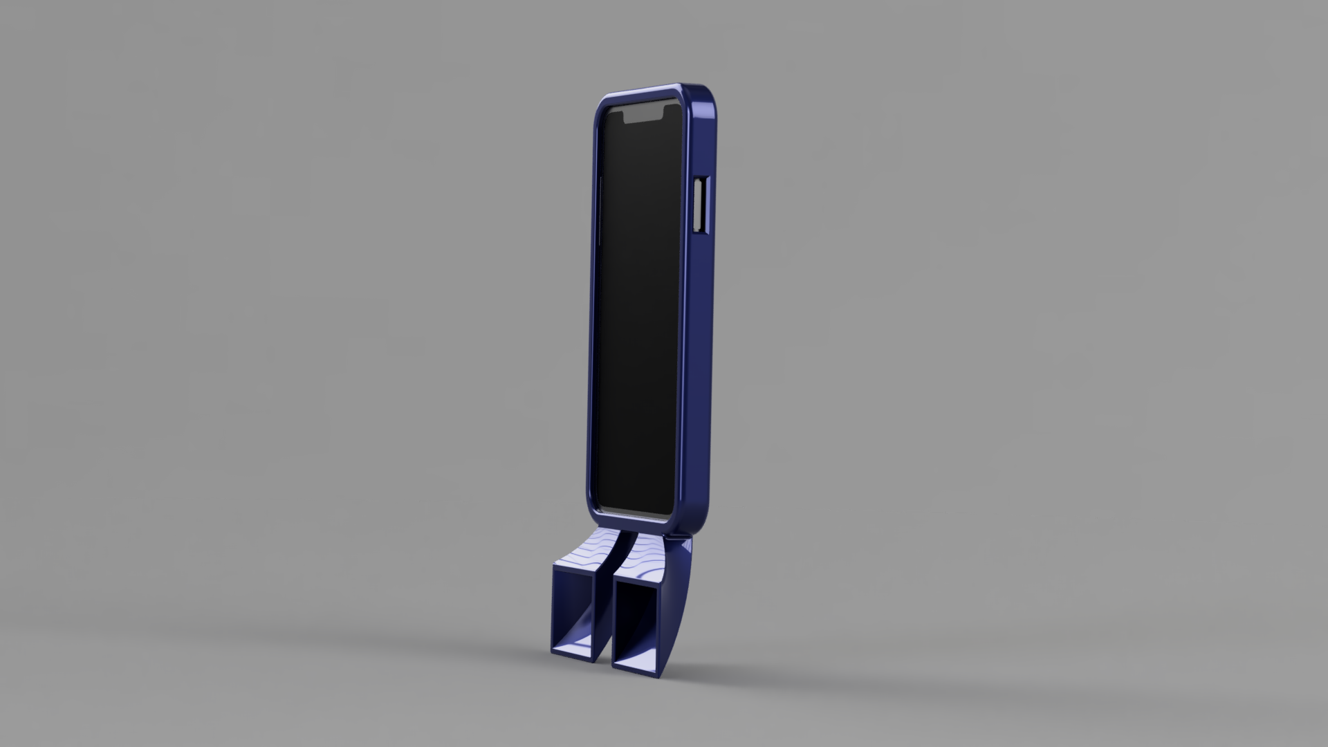
- The case was designed with a wall thickness of 2 mm and a back thickness of 3 mm.
- These thicknesses were selected to provide ample protection for the phone, as they were thick enough to protect the phone against a drop but still thin enough to maneuver the case onto the phone itself.
- The buttons were made accessible by designing cutouts for the power and volume buttons with 2 mm offsets.
- Chamfers were also used on the button cutouts to taper the edges and improve accessibility.
- The touchscreen was protected using a top lip that extended from the side walls over the top surface of the phone screen.
- This lip extended 3.5 mm onto the phone screen, which was a large enough distance to hold the phone in place and protect it.
- Based on the “Display Active Area” in the Apple Design Guidelines technical drawings, it was also a small enough overhang to not interfere with the touchscreen.
Functional Component
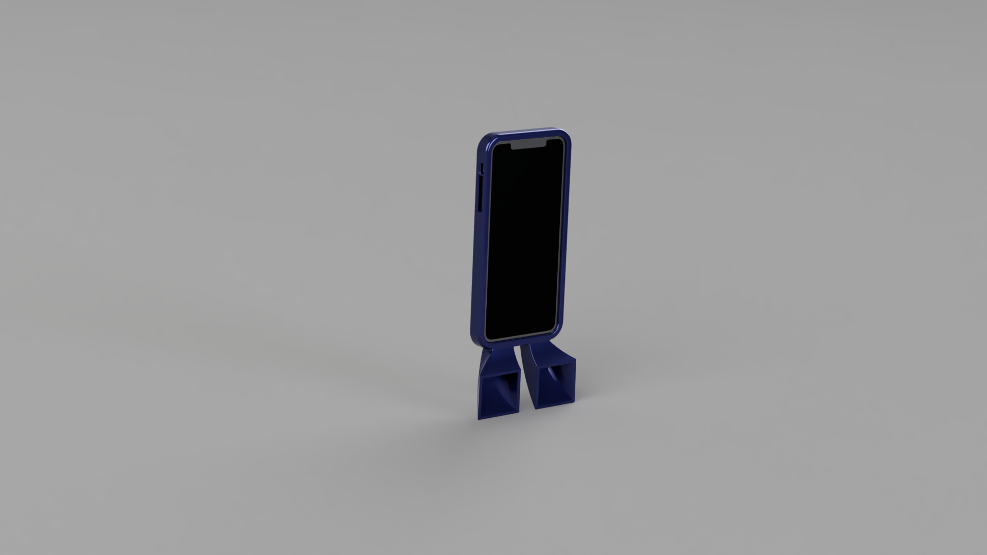
- The functional component incorporated into this phone case design was a lofted set of speakers.
- These speakers redirect the sound from the bottom speakers at a 90 degree angle towards the user, allowing the user to hear audio from their phone more clearly while also amplifying the audio.
- The bottom speakers on the iPhone are adequate and provide solid audio quality; however, their positioning perpendicular to the screen is not conducive to the user’s listening experience when consuming content.
- Angling the sound towards the front where the user views content on the screen allows for an enhanced experience where the user can consume content on their phone with clear audio without needing to cup their hands near the speakers.
- Additionally, the larger output holes of the speakers allow for natural amplification of the phone’s audio, which can be useful for sharing audio content in a group setting.
Parametric Modeling
- Parametric modeling was used to quickly iterate between different versions of the phone case design.
- While the case can be designed to fit perfectly with the phone’s design dimensions, in reality, fused filament fabrication (FFF) 3D printing has some results in some variation in size and fit of the phone case.
- By parametrizing key dimensions of the phone case in the CAD design itself, these dimensions were able to be quickly adjusted between prototype versions based on the fit of the case each time.
- This allowed the time spent between iterations on revising the case design to be much shorter and also limited mistakes in adjusting the dimensions of the design for a better fit.
Material Selection
- The filament used for 3D printing the phone case was thermoplastic polyurethane (TPU) with shore hardness of 95A.
- TPU is a flexible elastomer that combines the performance benefits of rubber (i.e. great toughness and chemical resistance) with the easy processability of thermoplastics, allowing it to be 3D printed.
- It has high tear and abrasion resistance, making it ideal for a phone case that should protect a phone and be flexible enough to wrap around the phone.
- It also exhibits low shrinkage due to its elastomer properties despite also a semi-crystalline hard segment.
Slicer Settings
- To print TPU, certain settings needed to be adjusted in the slicer software from what would be needed to print a more traditional plastic, such as PLA.
- Since TPU is more elastic than traditional rigid plastics, it requires slower print speeds since the filament is harder to grip and push on.
- Without this adjustment, printing TPU on traditional rigid filament settings would result in a jam in the extruder.
- The temperatures of the extruder and the bed were also adjusted, with the bed temperature matching the glass transition temperature of TPU.
- None of the default TPU slicer settings were changed for the first two iterations printed on the Voron printers. The third iteration was printed on the MakerGear printer at a lower temperature, allowing for better detail on the surface of the phone case.
Benefits and Limitations of FFF Printing
- In terms of quickly iterating between different versions of prototypes, FFF printing allows for many iterations with slight variations to be churned out quickly.
- This is due to the quick setup times associated with the 3D printers as well as the relatively low cost of materials associated with FFF printed compared to traditional manufacturing techniques.
- FFF printing is limited by the fact that the final printed part is only an approximation of the 3D model, discretized into layers.
- For the phone case, this particularly affects the curved fillets and edges that are not perfectly round in the final part.
- Additionally, the layered nature of the part leads to anisotropic mechanical properties where the part is weaker in one direction along the layer lines.
- For the thinner portions of the case, such as the speakers, this impacted the strength of the part and holes were able to be poked through certain parts.
Conclusions
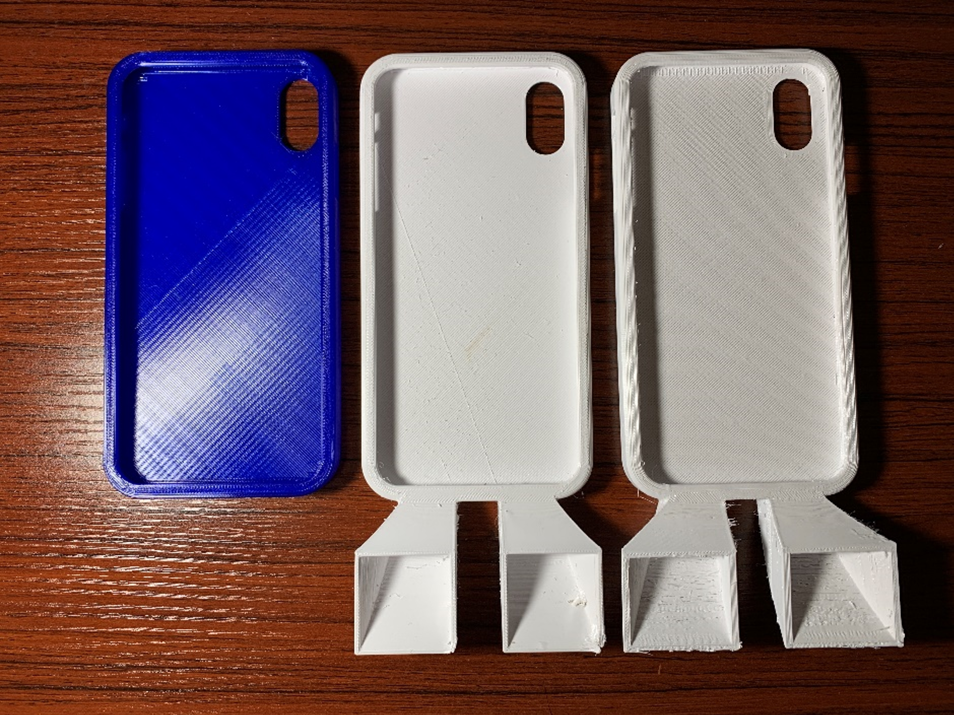
- Overall, all the iterations of the phone case printed successfully.
- The first iteration had a small amount of stringing on the inside between the side walls.
- This was not an issue that could be fixed by adjusting the 3D model; instead, it was likely an issue with poor retraction in the extrusion drive.
- The second iteration incorporated the functional aspect of the two speakers.
- This iteration highlighted some of the issues with the anisotropic mechanical properties.
- As mentioned above, the thinner walls on the speaker were weaker along the layer lines.
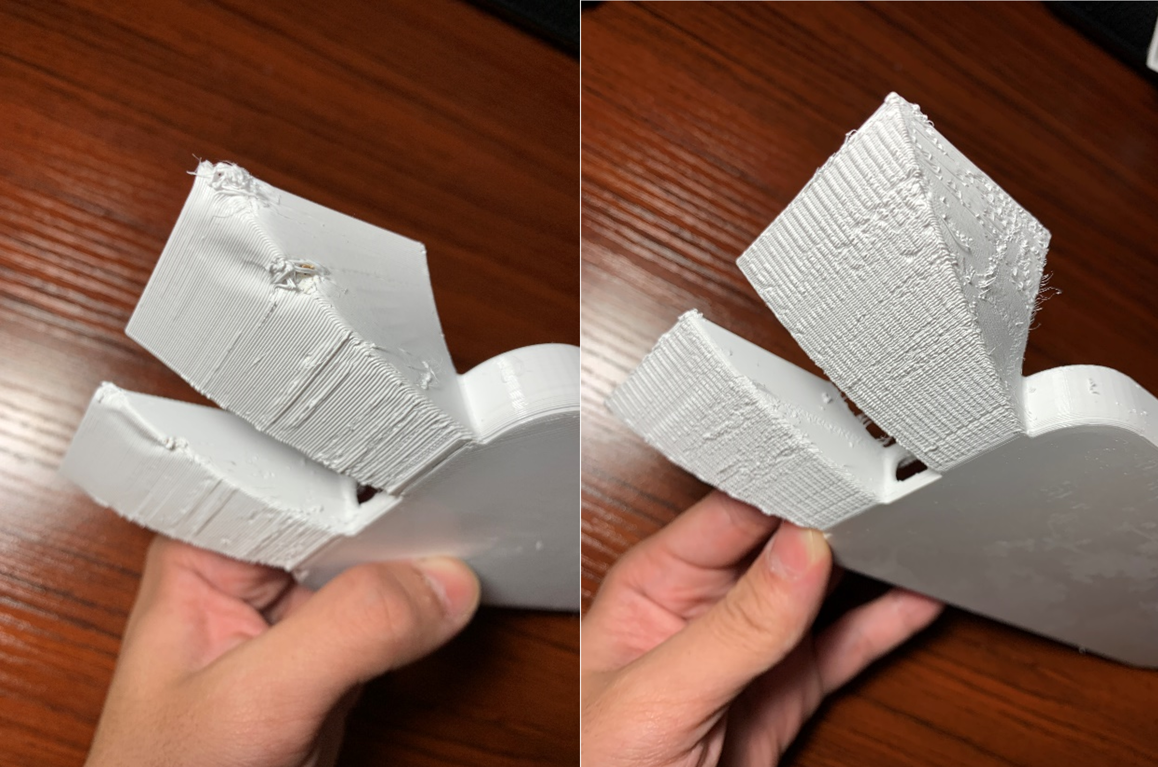
- They were able to be pulled apart and a hole was found on one corner of the speaker as seen below in Figure 3.
- While the weakness along the layer lines contributed to this, the main reason for this was how thin the part was.
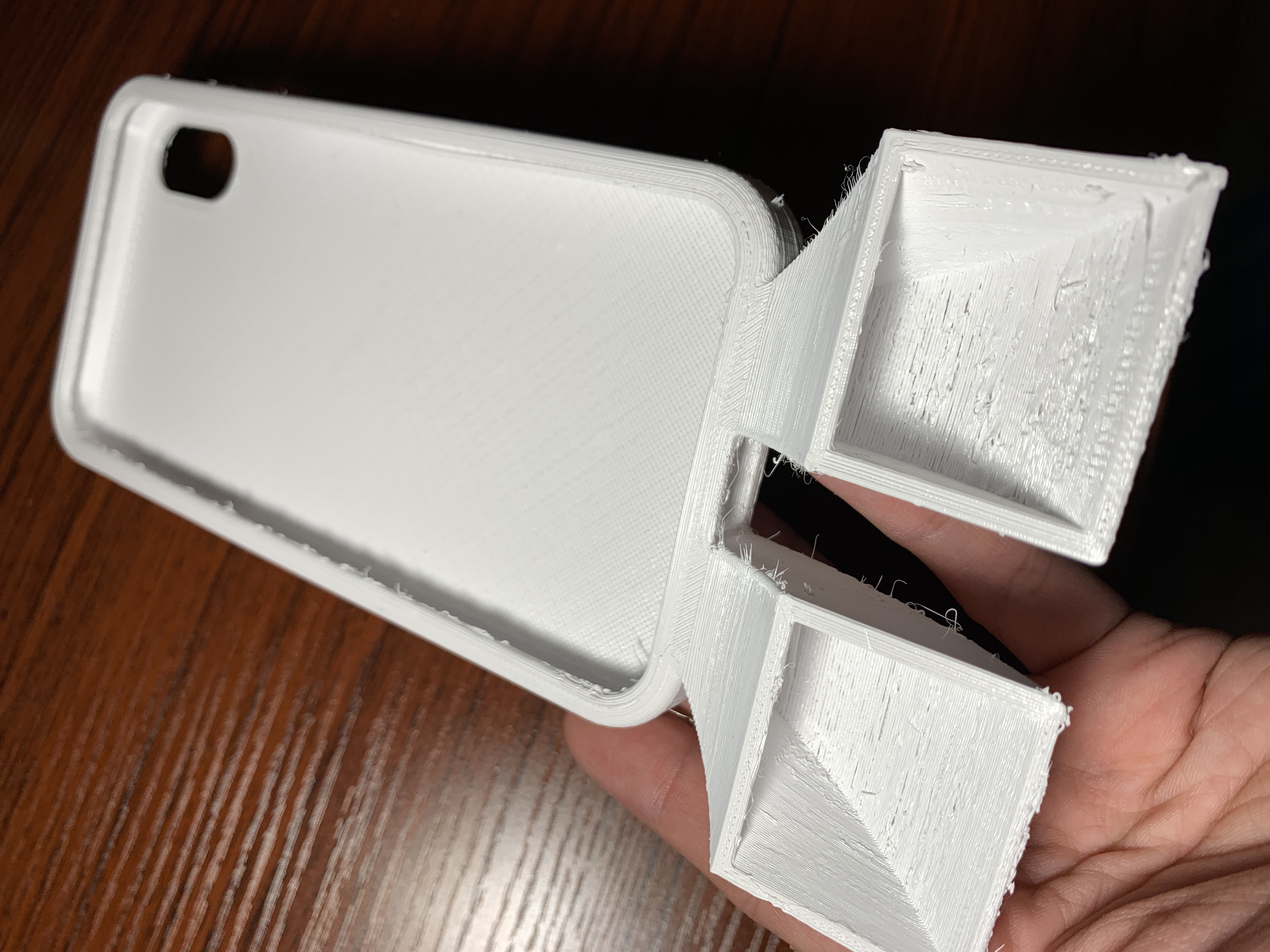
- The thickness of the speaker walls was adjusted in the 3D CAD model for the third iteration.
- While the walls are clearly thicker than the second iteration as seen below, the print quality was significantly lower, particularly in the speaker section.
- Layer lines were rough and clearly visible, and the supports that printed with the speakers caused several tears between layer lines.
- For future iterations, since the overhang of the speakers were all designed to be less than 45 degrees, a print without supports at that location could be attempted for a better surface finish quality.