Print-in-place models are a 3D printing concept where fully functional objects with movable parts can be designed and printed in a way that they work immediately after removal from the print bed.
This concept is often shown in Hollywood representations of 3D printing, where no post-processing (i.e. removing support material) or assembly is required and functional parts work directly off the print bed.
Print-in-place models can be created with traditional single material extrusion 3D printing by designing and orienting the object so there is ample clearance at joints to allow for motion or rotation.
However, these parts are often unable to achieve smooth motion due to the material properties of solid plastic and the irregularities that arise from plastic FFF extrusion.
The capabilities of dual extrusion 3D printing can be leveraged to improve the motion of functional print-in-place parts.
Flexible materials, such as thermoplastic polyurethane (TPU), can be incorporated into these models to allow for smoother actuation of the functional mechanisms.
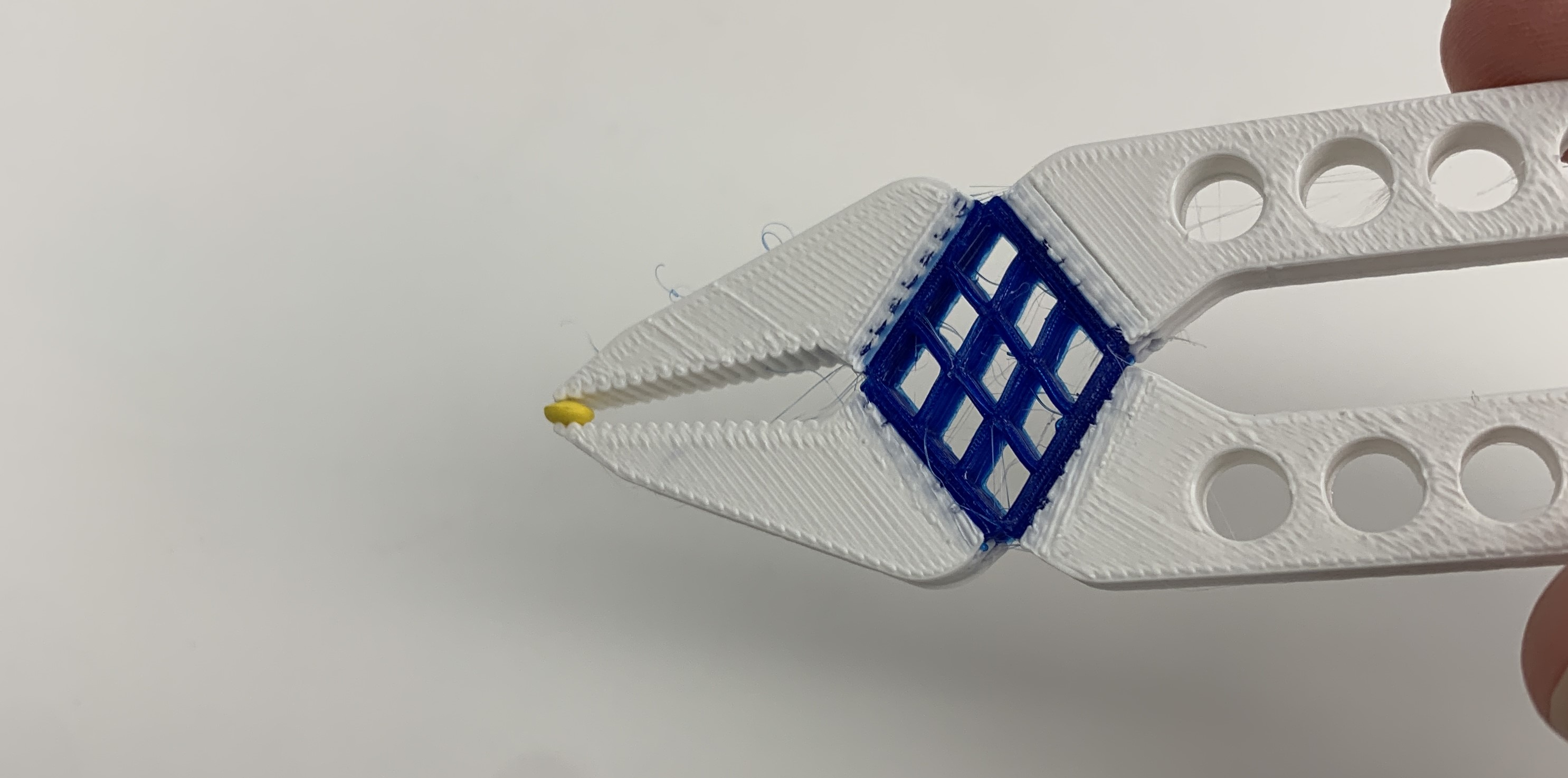
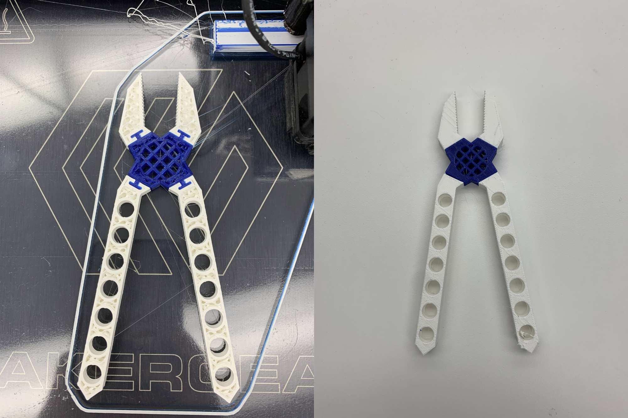
To demonstrate the capabilities of dual extrusion 3D printing for functional print-in-place parts, flexible needle nose pliers were created using both PLA and TPU that are capable of gripping and picking up a 3 mm diameter plastic pellet.
Video
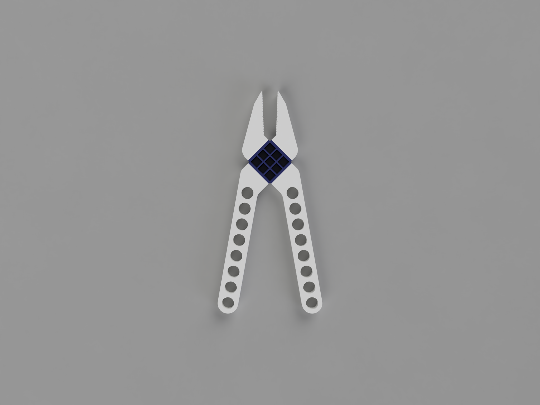
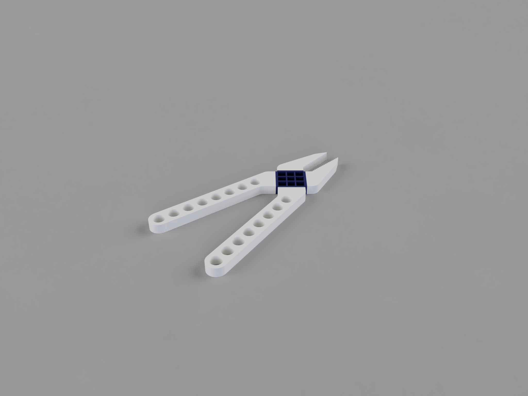
CAD Model
Design
Materials and Print Settings
Traditional PLA filament was used for the hard plastic components (handles and tips). TPU 95A was used as the flexible filament for the spring component.
A MakerGear M3-ID printer with 0.35 mm dual extrusion nozzles was used to dual extrude both filaments.
The pliers were printed with wipe tower enabled to purge each nozzle prior to switching extruders for each layer, and to reduce the amount of ooze contamination in the part itself.
This was particularly necessary for the TPU filament, which oozed a substantial amount when idle.
For most layers, the TPU extruder did not start extruding until over half its layer on the wipe tower was printed.
While the wipe tower was necessary, the size of the wipe tower was decreased from a width of 60 mm to 40 mm to optimize the time and material required to print the pliers.
The bed temperature was set to 60 C, nozzle 1 (PLA) was set to 215 C and nozzle 2 (TPU) was set to 240 C.
The maximum speed of the TPU extruder was capped at 25 mm/s to ensure that the extrusion gear did not grind the TPU filament too quickly and cause a jam. The retraction speed of the TPU extruder was capped at 15 mm/s.
Flexible Spring Component
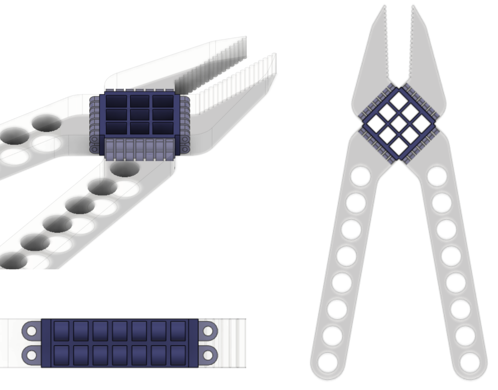
A 3x3 TPU square lattice was used as the flexible spring component.
This allows the plier tips to close when the handles are squeezed, but also reverts back to the original ‘open’ position when the handles are released.
A square lattice was selected so that the square shape would be able to flex into a parallelogram.
Due to the nature of the flexible TPU and the square lattice shape, the joint is also able to flex outwards when the handles are pulled apart. This allows for the maximum jaw capacity to actually increase beyond the resting jaw capacity.
Interface Connections
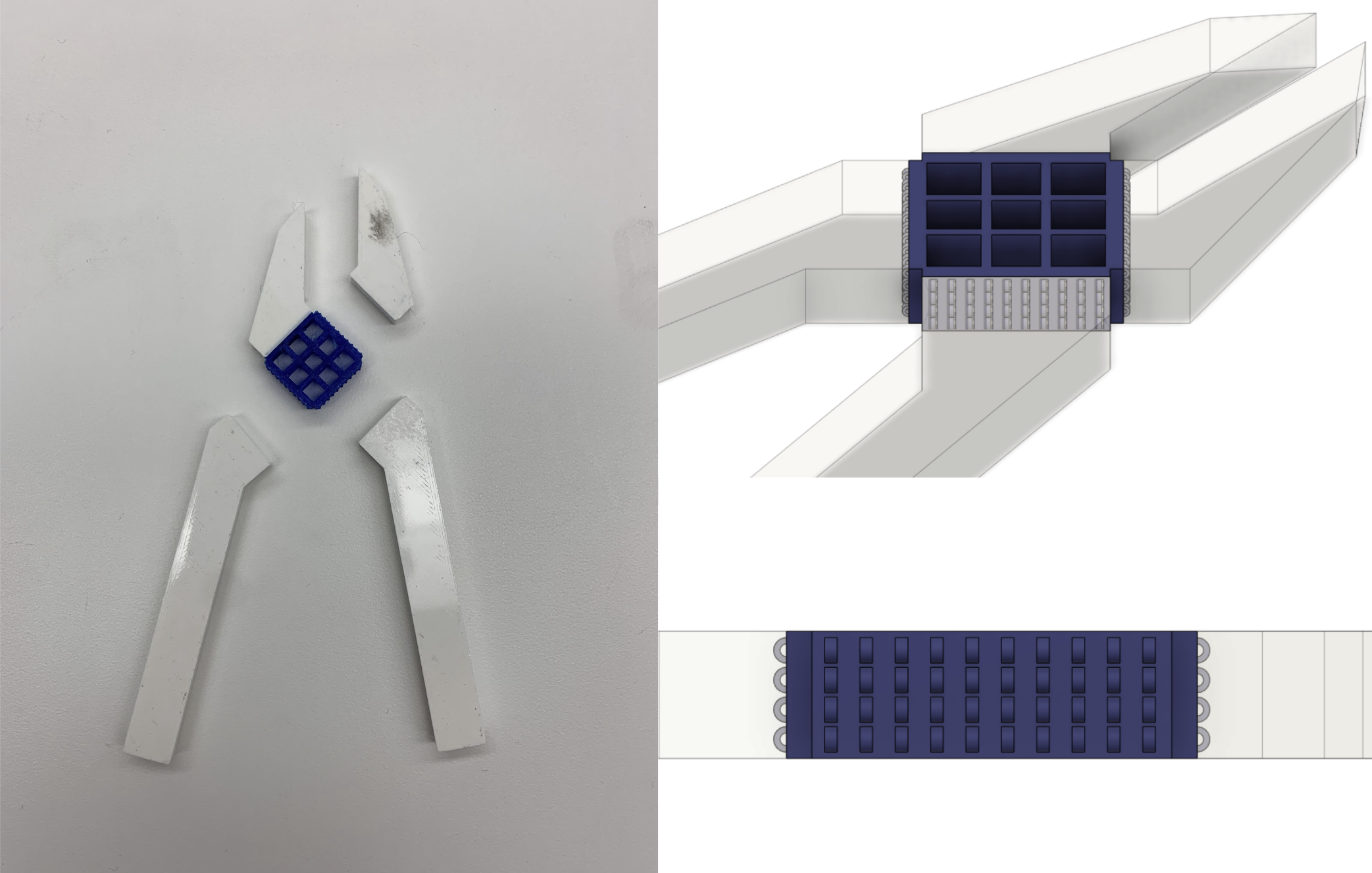
Since PLA and TPU do not stick together naturally, a mechanical joint mechanism was needed between the TPU and PLA parts to ensure that the handles and tips stayed connected to the flexible spring component.
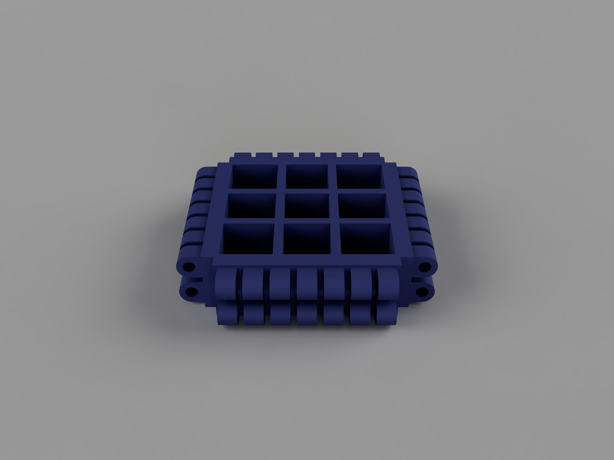
The capabilities of dual extrusion 3D printing were leveraged to create an internal hook and loop mechanism.
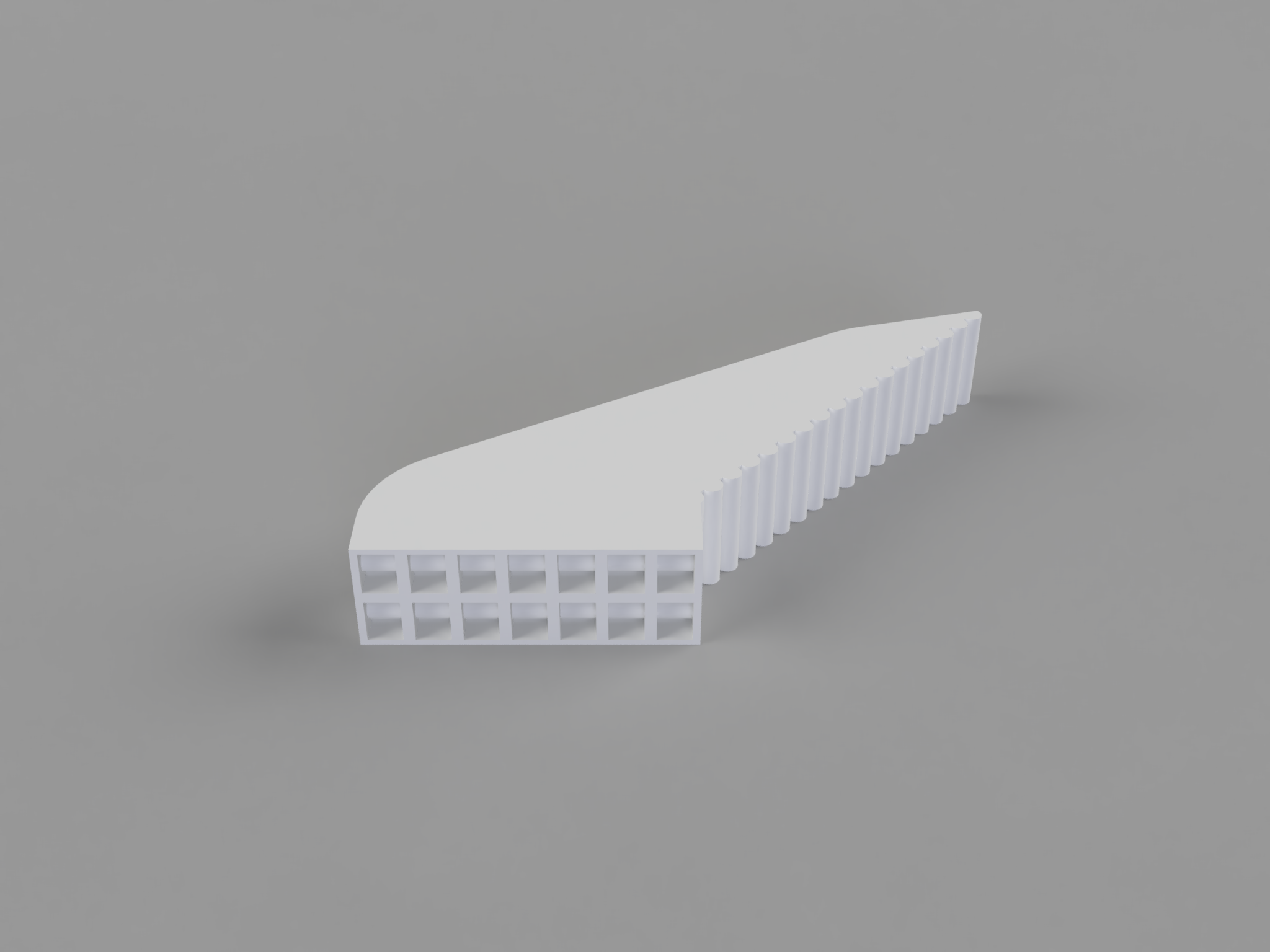
Each connection face has a 2x7 grid of hook and loop connectors.
TPU hooks loop through PLA rods that are inside the PLA components.
As each layer is printed, the PLA rods are enclosed by the TPU hooks around them, physically constraining the two parts together.
This joint mechanism can only be made with dual extrusion 3D printing since there are internal overlaps between different components.
PLA Components
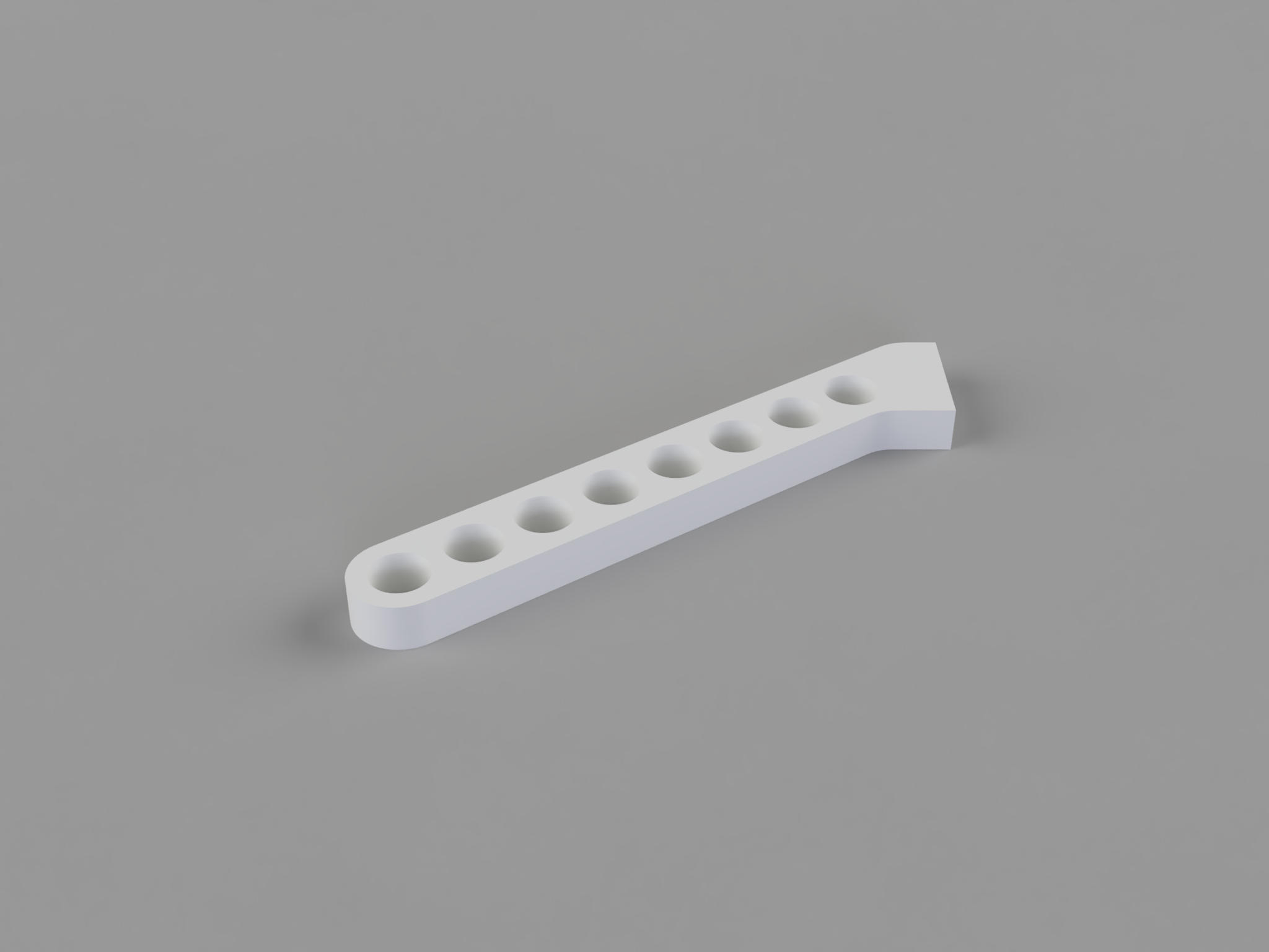
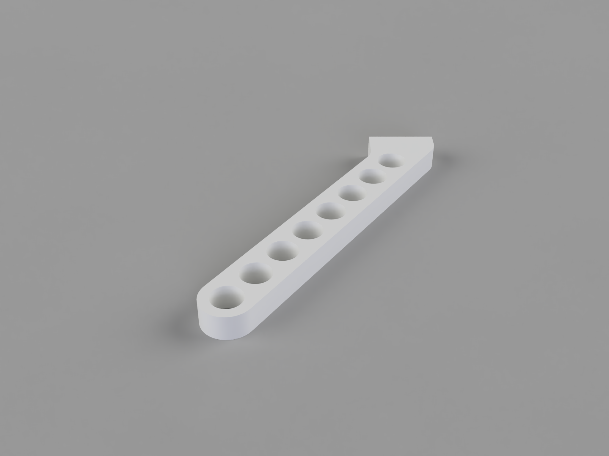
Circular cutouts were added to the handles to decrease the amount of filament used and to minimize print time.
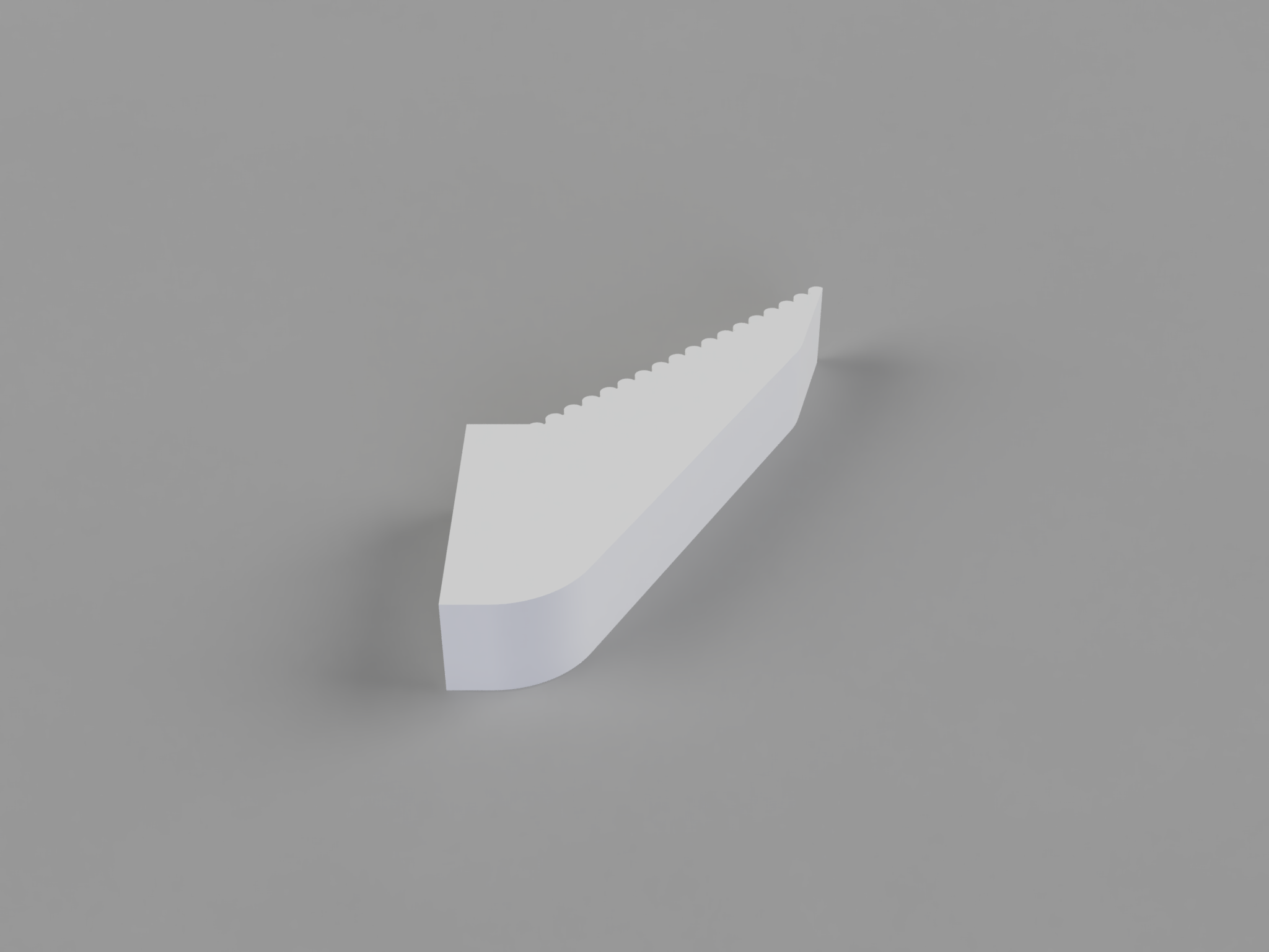
Small, semicircular ridges were added to the tip surfaces to increase the gripping abilities of the pliers.
Phyiscal Specifications
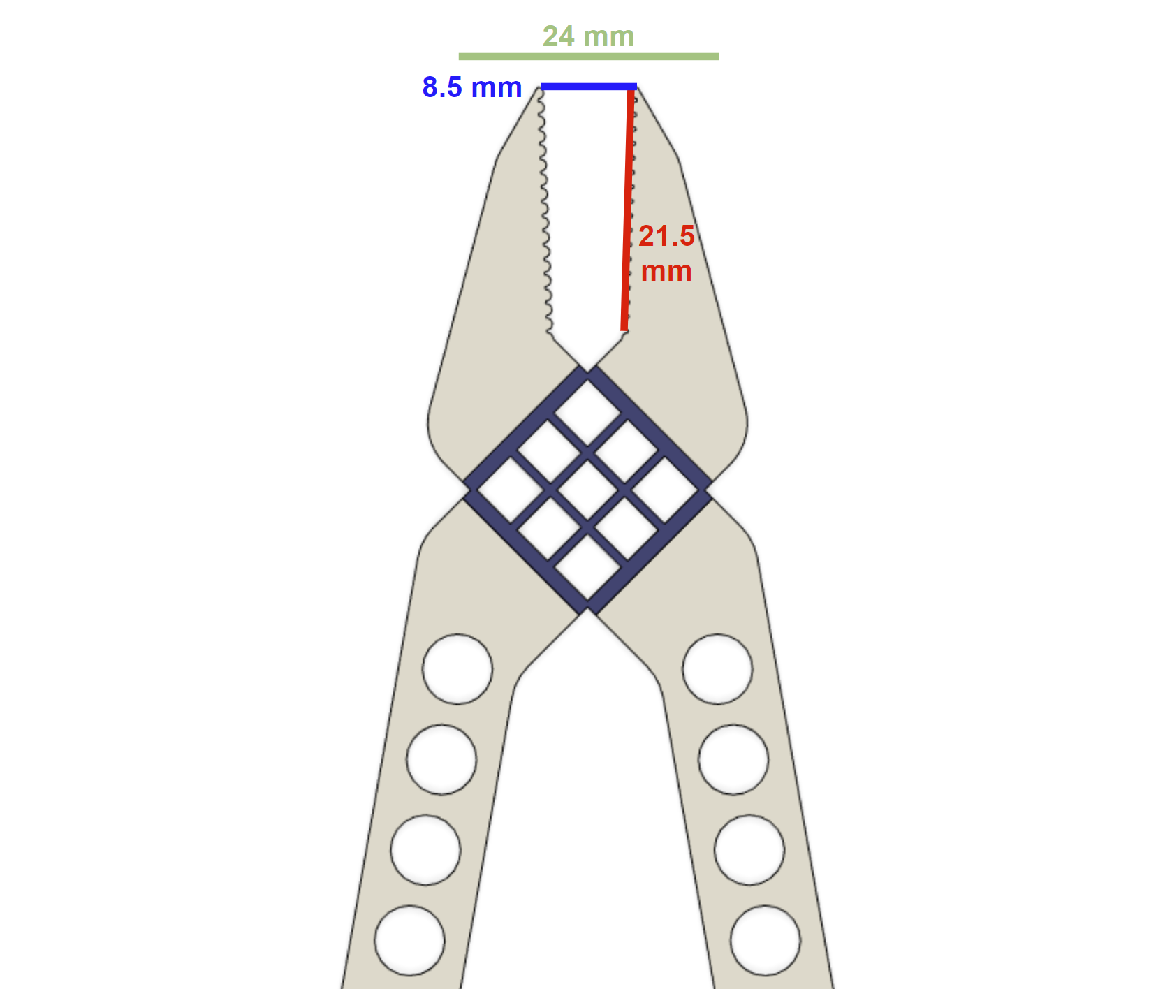
Jaw Length: 21.5 mm
Resting Jaw Capacity: 8.5 mm
Maximum Jaw Capacity: 24 mm
3D Printed Components
Component
Image
Joint
Handle (Left)
Handle (Right)
Tip (Left)
Tip (Right)
Design Progression
Version 1
Version 1 of the pliers used a single T-shaped internal joint mechanism to connect the PLA and TPU components.
This proved to be too weak to firmly hold the two materials together. When the handles were squeezed, the PLA would separate from the TPU with a lot of wiggle room left over.
A circular-shaped lattice was used for the flexible joint component.
The circular shape of the matrix prevented the squares inside it from flexing into a kite shape, which was necessary to transmit the force of the handles being squeezed to the tips.
The corners of the flexible joint piece also proved to be too thick to properly flex. Even when the tips were directly pressed towards each other, they would move very minimally due to the TPU acting almost as a non-flexible material because of the thickness.
Version 2
Version 2 moved away from the T-shaped internal connectors to the hook-and-look connection mechanism. However, the TPU hooks used in V2 proved to be too small.
The holes in the hooks were too small to allow a substantial amount of PLA to be deposited within them, preventing a strong PLA rod from being formed that the hook could attach to.
This was improved in Version 3 (the final version) by increasing the size of each individual hook and loop and decreasing the number of hooks and loops used.
The flexible joint component was changed from a circular shape to a square shape.
This was much improved from V1, allowing the entire joint to flex and then return to its original position.
The thickness of TPU used was also decreased in V2, which resulted in much more flexible behavior.