Microfluidic Mixer
Background
- Microfluidic mixing aims to achieve thorough and rapid mixing of multiple fluid samples on a microscale level
- The small size of the flow channels in these mixers increases the surface to volume ratio when compared to macro-scale mixers, making these devices useful in many applications
- These devices have a considerable impact on the fields of biomedical diagnostics and drug development as well as the food and chemical industries
- Specific applications of microfluidic mixing include:
- Sample dilution
- Reagent homogenization
- Chemical or biological reactions
- However, the microchannels present a challenge due to the Reynolds numbers in the channels
- For example, typical water-based microfluidic systems have Reynolds number on the order of 0.1
- Contributing factors include:
- Small hydraulic diameter
- Low kinetic viscosity
- Low flow velocity of the solution(s)
- Unlike larger macro-scale mixer devices, turbulent mixing does not occur in these low Reynolds number regimes.
- Flows in microfluidic devices are almost always laminar in nature, making thorough mixing a key challenge within microfluidics since these devices cannot take advantage of turbulent mixing.
- As a result, microfluidic homogeneous mixers rely solely on diffusive mixing
- Diffusive mixing is an inherently slower process and requires a long channel to achieve sufficient mixing
- The aim of microfluidic mixing schemes is to enhance the mixing efficiency by speeding up the time required to achieve adequate mixing, and/or by shortening the channel length required
- There are two approaches to microfluidic mixing: active and passive mixers
- Active mixers: improve the mixing performance by applying external forces to the fluid flows to accelerate the diffusion. Active mixing schemes include:
- Acoustic/Ultrasonic
- Dielectrophoretic
- Electrokinetic time-pulse
- Electrohydrodynamic force
- Thermal actuation
- Magneto-hydrodynamic flow
- Electrokinetic instability
- Passive mixers: the microchannel configuration is designed to increase the contact area and/or the contact time of both samples. While no external energy or stimulus is required, passive schemes typically result in a lower mixing efficiency than active schemes. Passive mixing schemes include:
- Lamination
- Zig-zag channels
- 3D serpentine structures
- Embedded barriers
- Twisted channels
- Surface chemistry
- Active mixers: improve the mixing performance by applying external forces to the fluid flows to accelerate the diffusion. Active mixing schemes include:
Design
Microdevice Fabrication
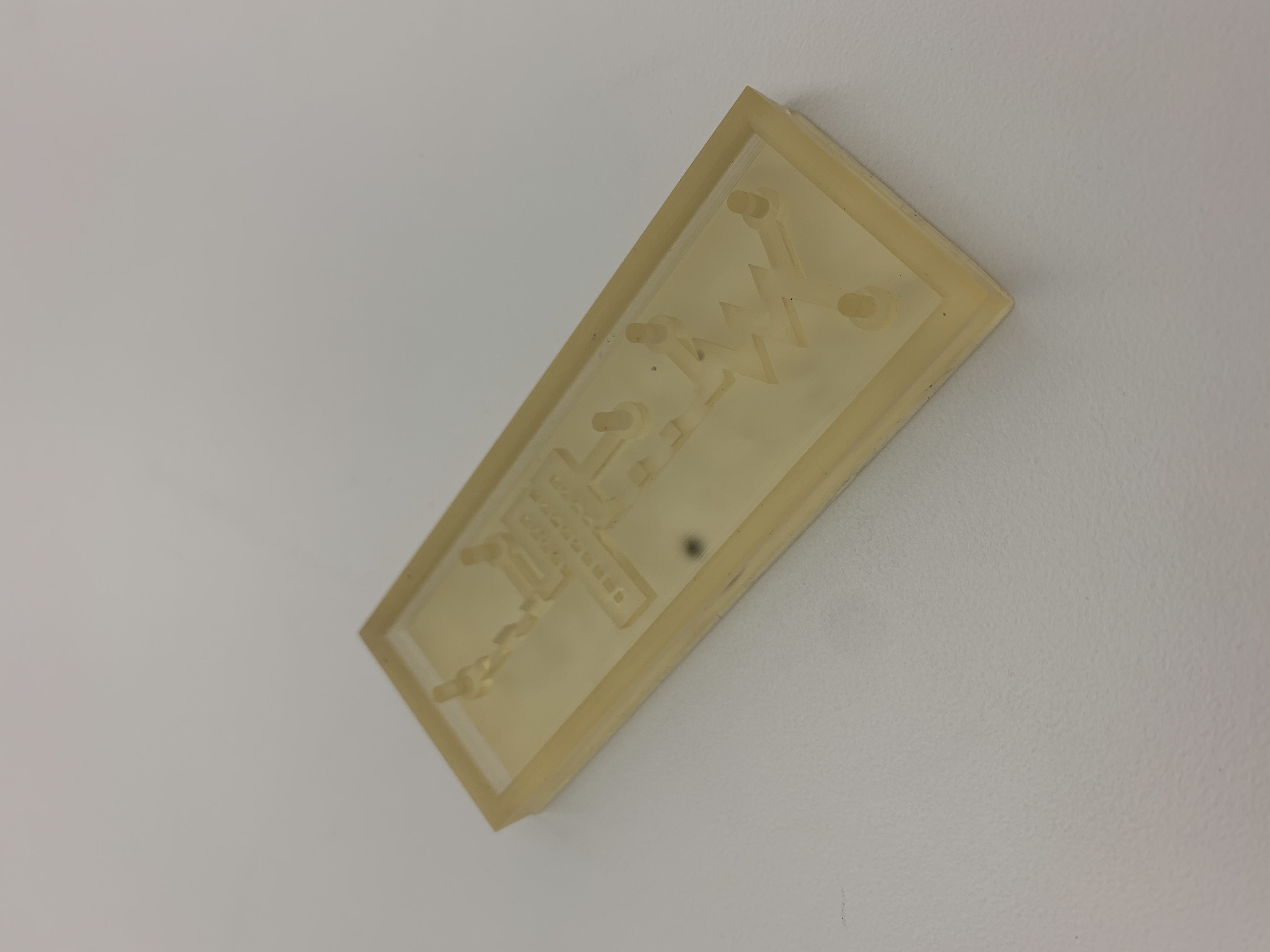
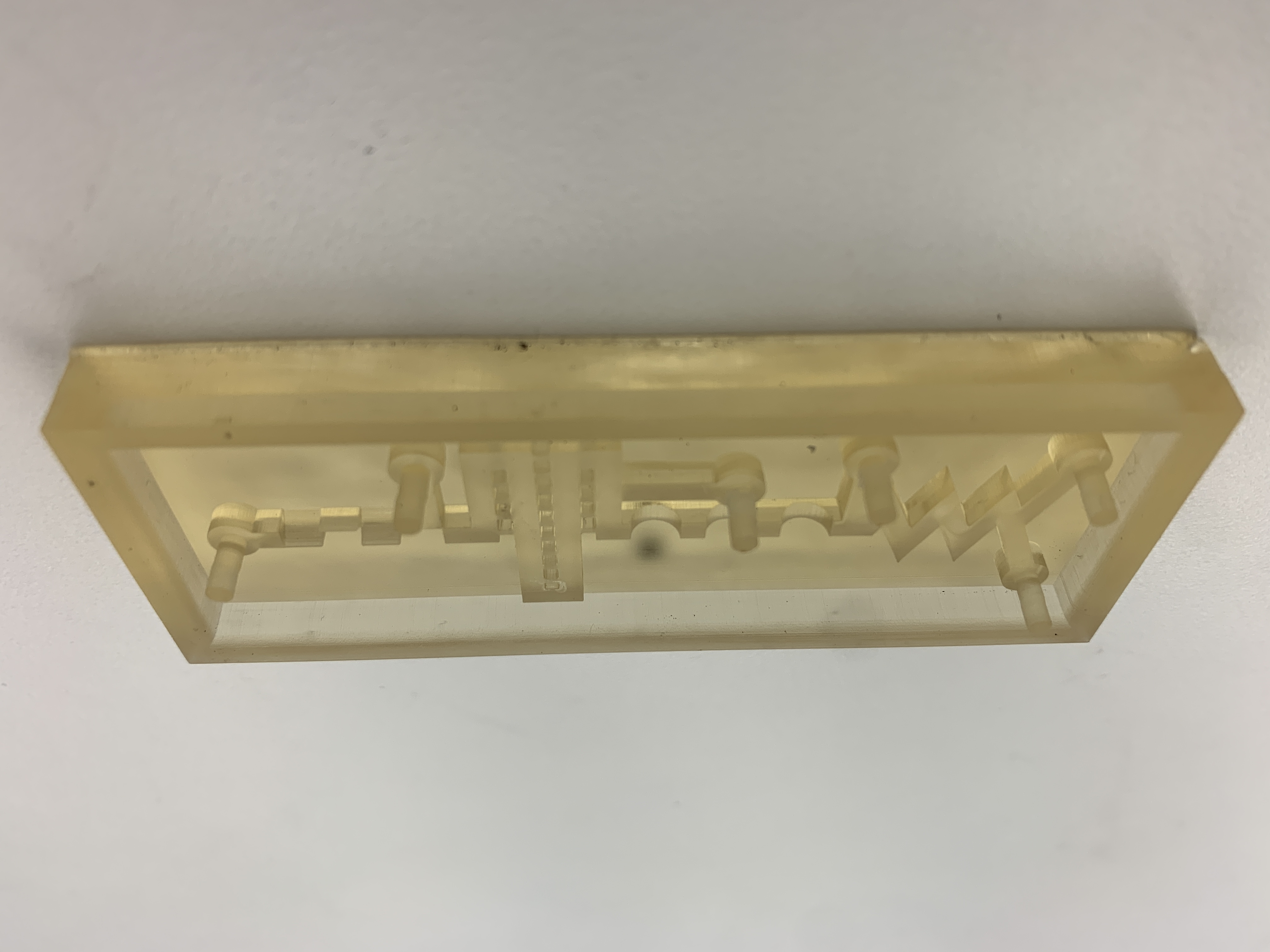
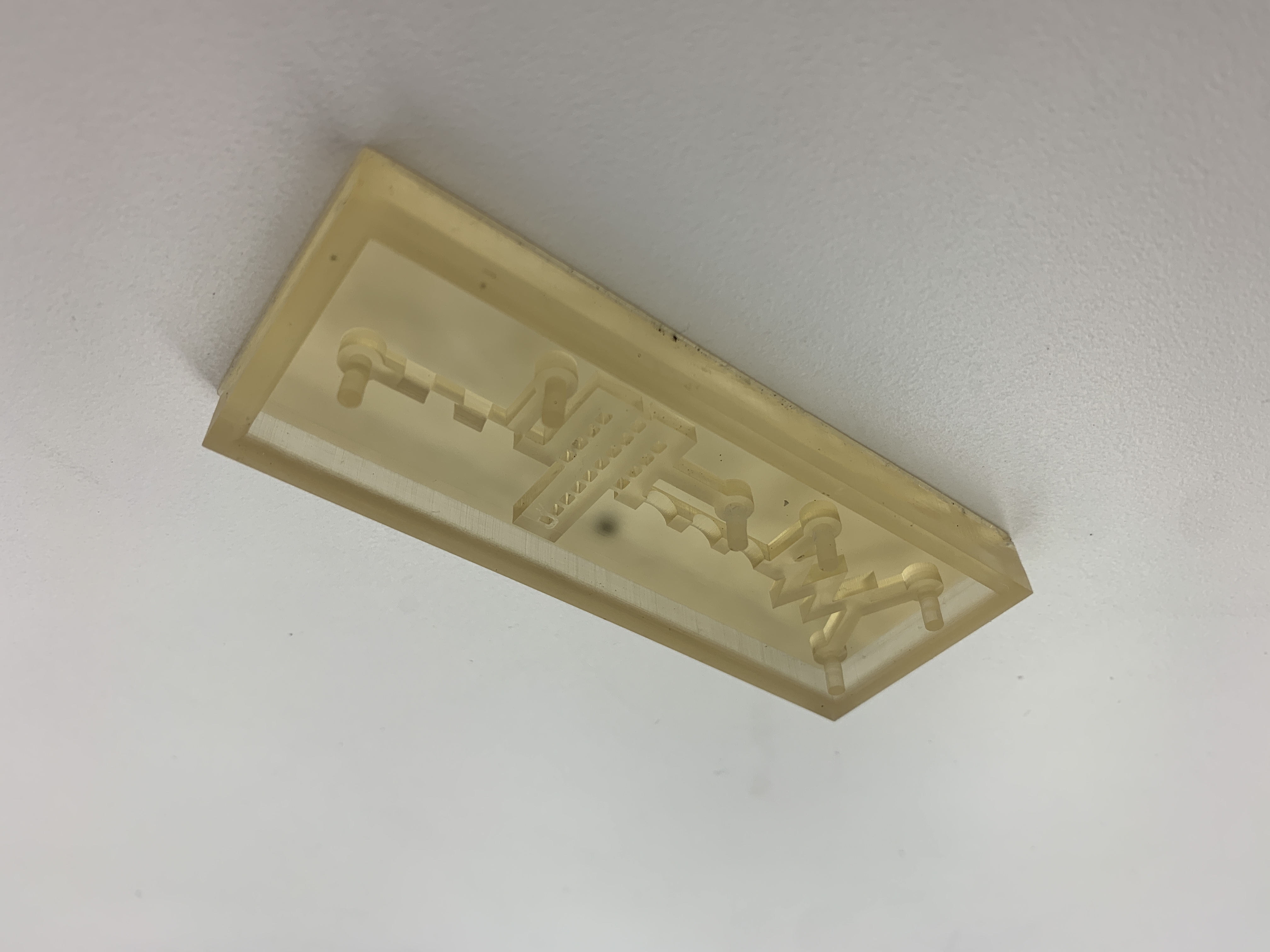
- A Form 3 stereolithography (SLA) printer was used to 3D print the negative mold of the microfluidic mixer
- The Form 3 provides minimum layer resolution of 25 um along the z-axis and 80 um resolution along the x- and y-axes
- Formlabs High Temp resin was used to print the mold
- Completed prints were washed with isopropyl alcohol until visible clean and cured with UV light for 60 minutes at room temperature
- Cured prints were then transferred to a Labcoter PDS 2010 parylene deposition machine (Specialty Coating Systems) and coated with 2 grams of parylene-C
- Polydimethyl siloxane (PDMS, Sylgard 184; Ellsworth Adhesive Company) elastomer and curing agent were mixed at a weight ratio of 10:1 and poured onto the print
- The mixture was degassed in the mold for 30 minutes in a vacuum chamber and cured at 80C for 3 hours
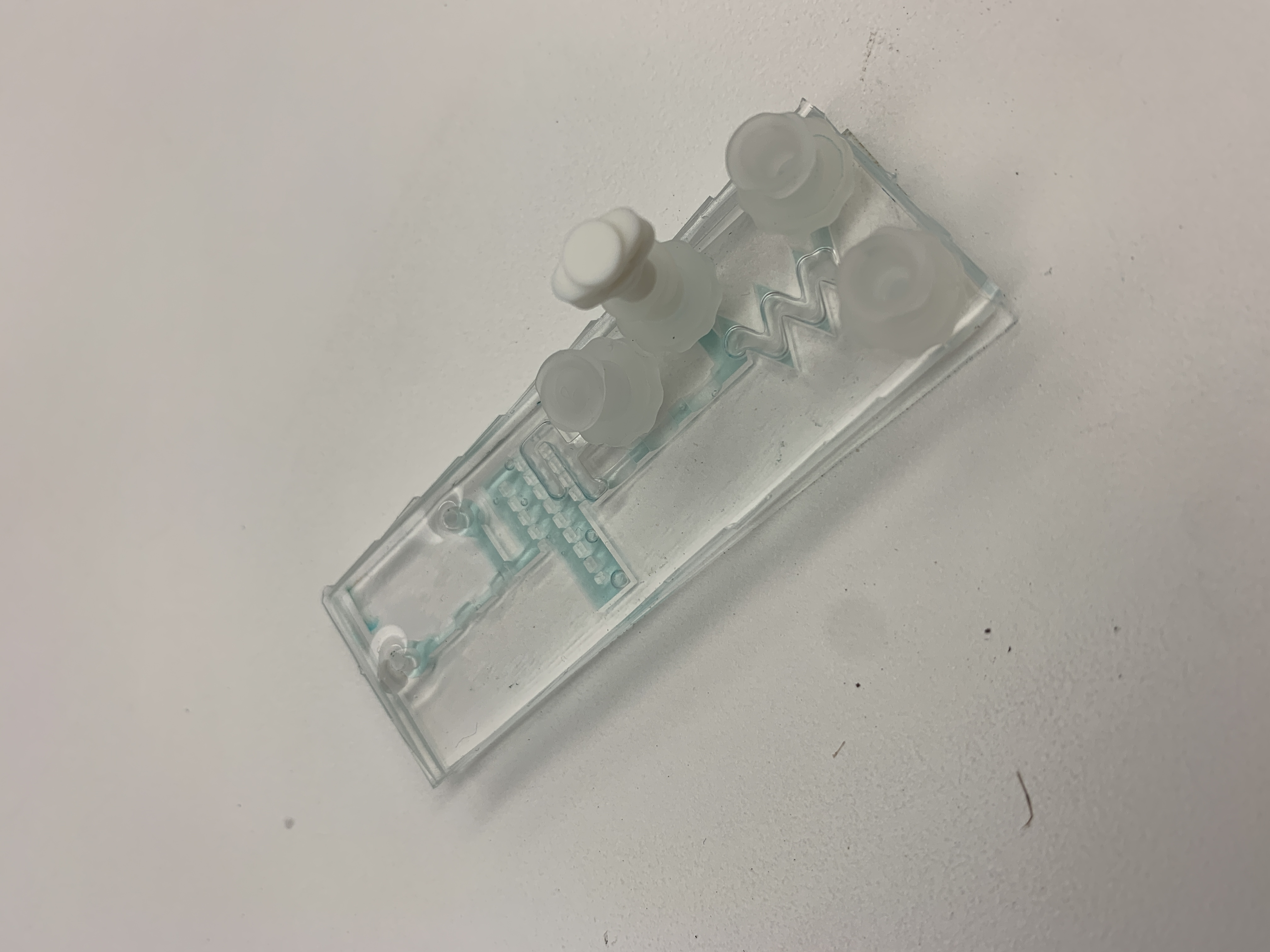
- After demolding, the PDMS device was bonded to common glass microscope coverslips using a PlasmaFlo PDC-FMG plasma cleaner (Harrick Plasma) and sterilized in an autoclave prior to use
Description
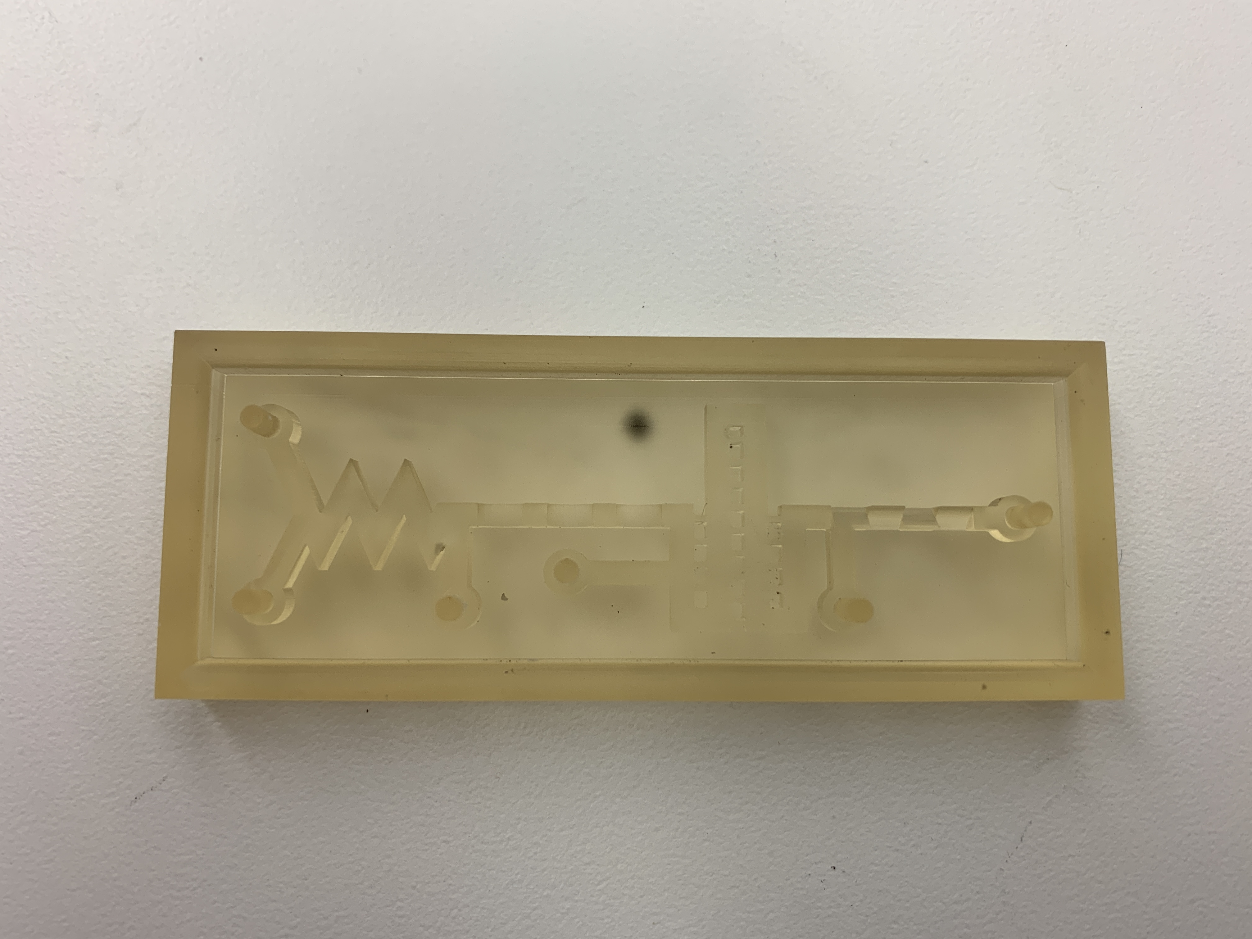
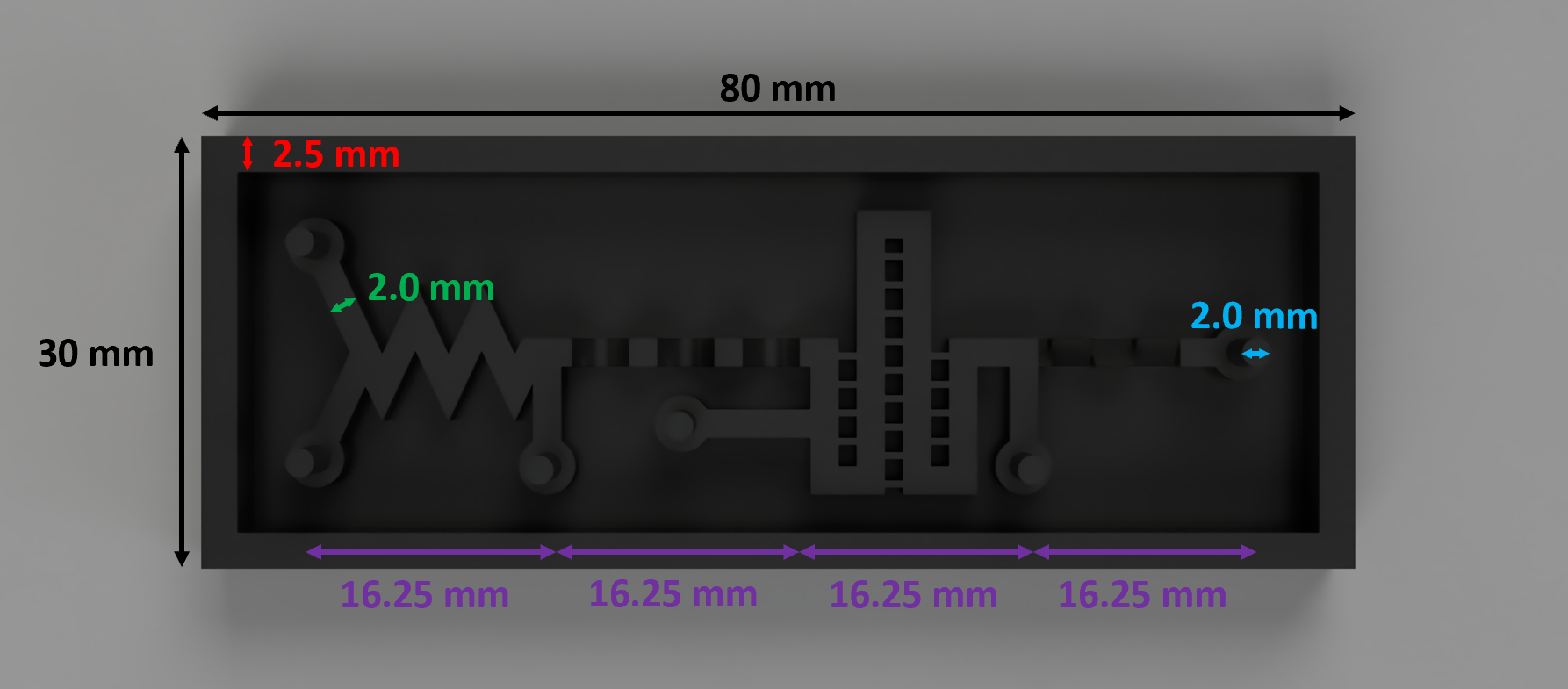
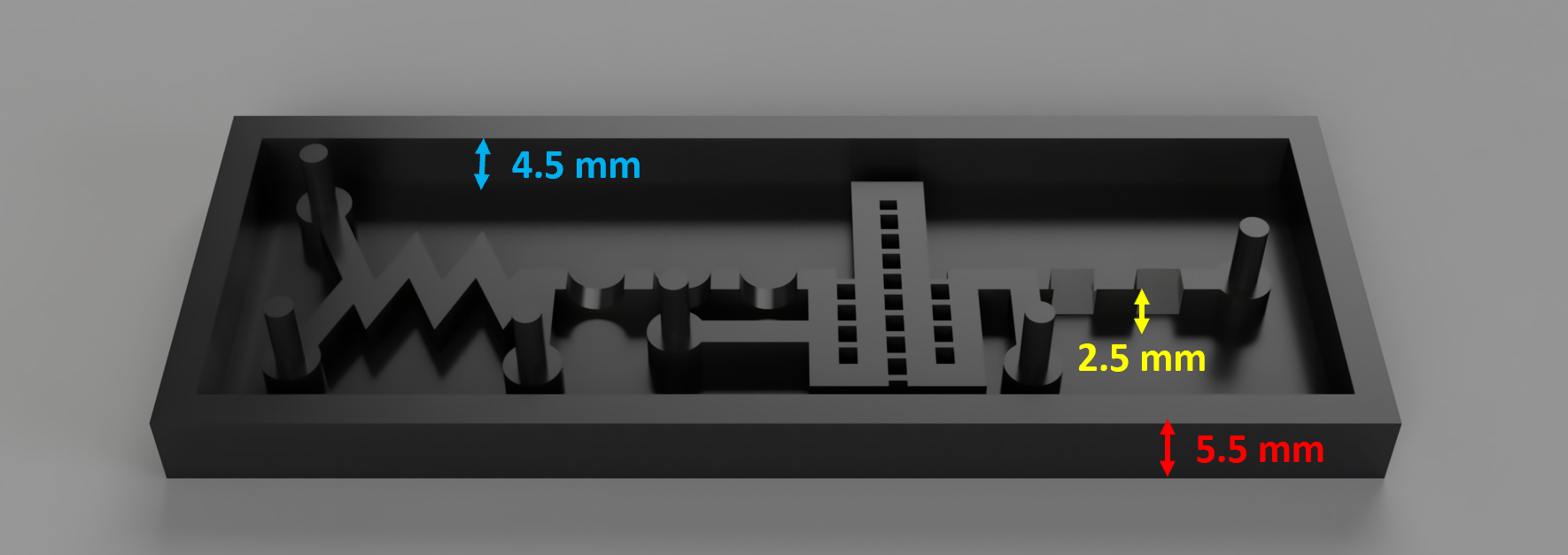
- The device has four sections, each using a different passive mixing scheme:
- Zig-zag channels
- Three-dimensional ridges
- Intersecting channels
- Inclined mixer
- The inclusion of 4 sections forces the two samples to mix both in the XY directions (sections 1 and 3) as well as in the Z direction (sections 2 and 4)
- 2.0mm diameter posts were included at both inlets and the outlet to create an interface for connecting to the microfluidic tubing
- Connection posts were also included in between each mixing section to evaluate the intermediate mixing results of each mixing scheme
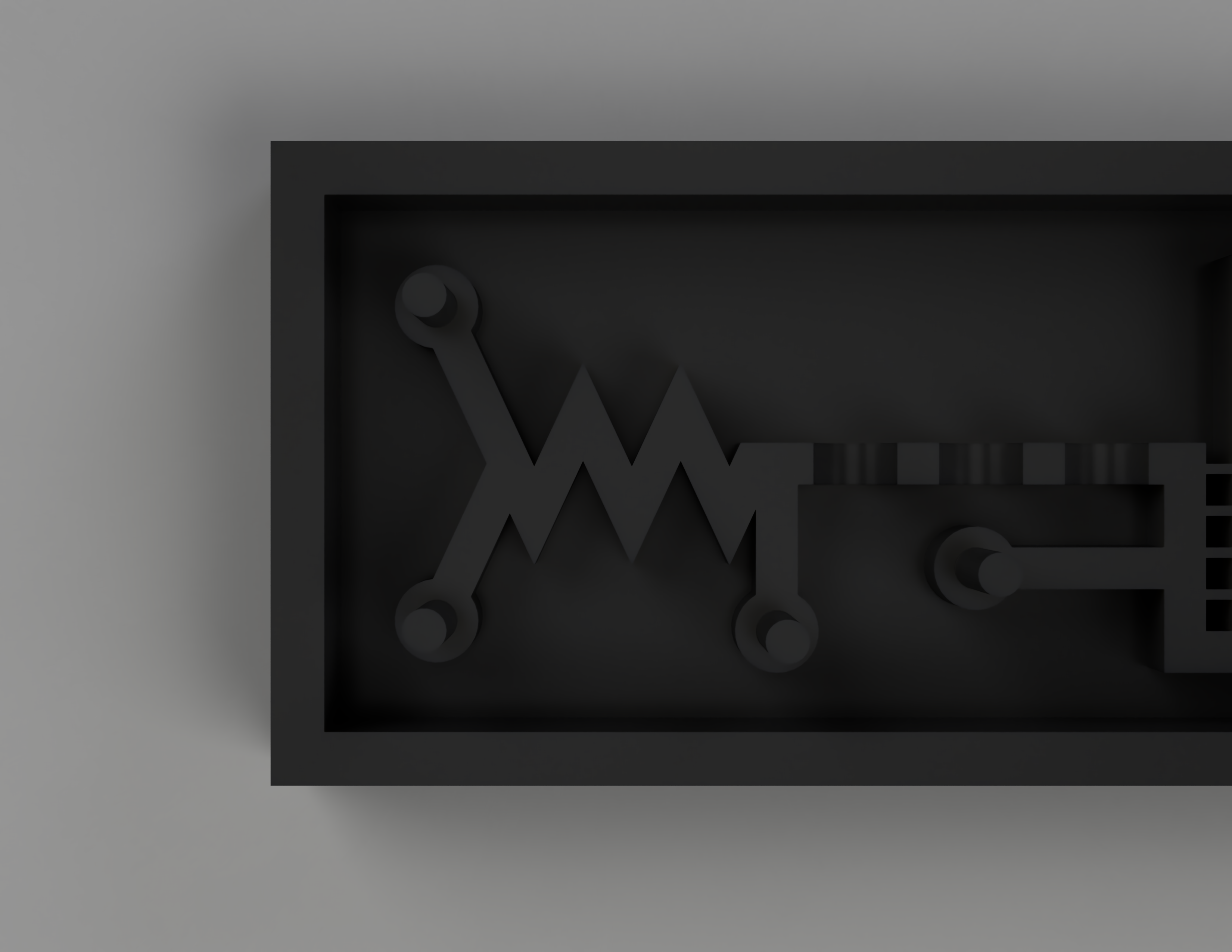
- Zig-zag channels are one of the most popular passive mixing methods due to it being control-free and relatively simple to design and fabricate
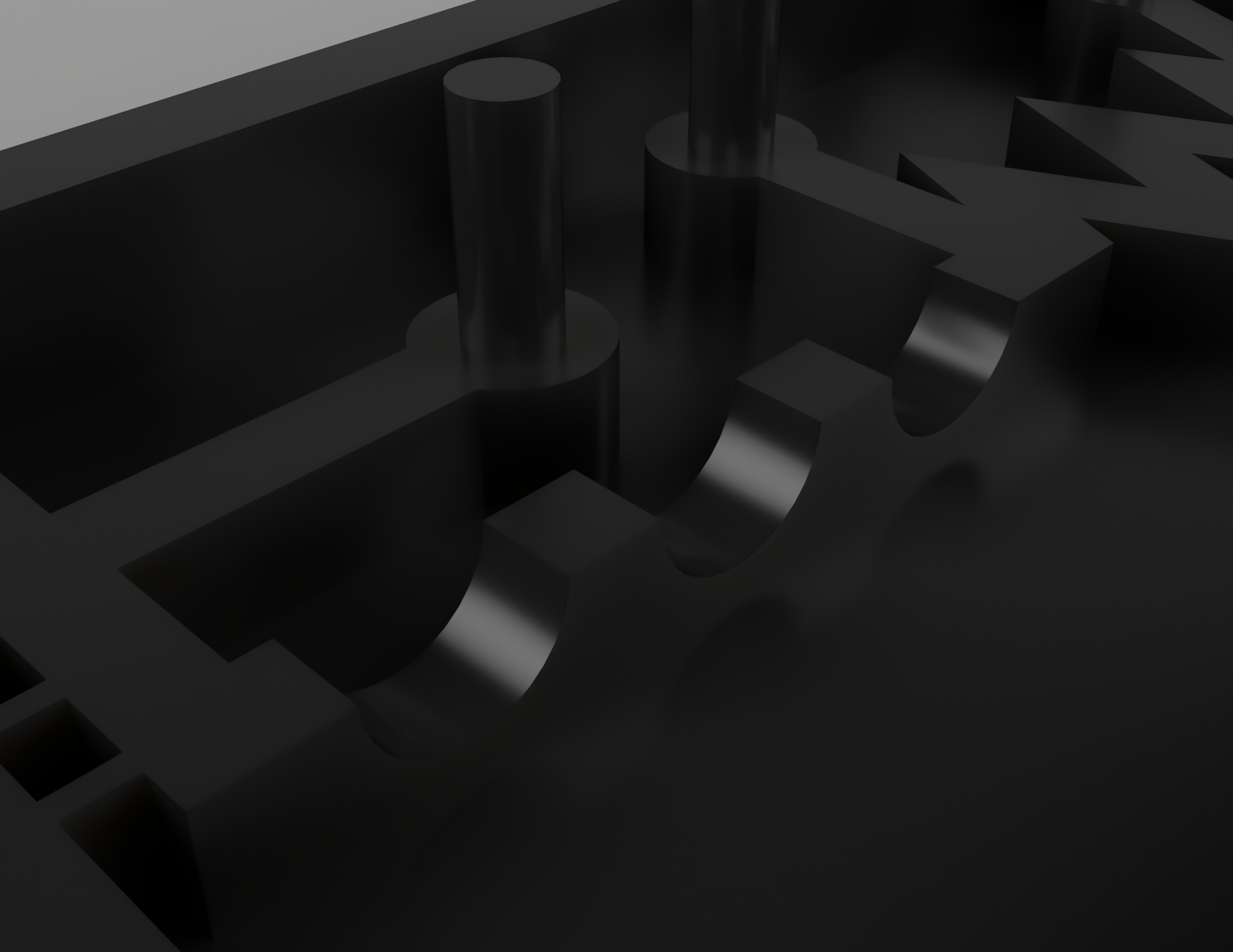
- The inclusion of 3D ridges is intended to induce chaotic advection in the mixer, particularly in the Z-direction, by forcing flows with transverse components to fold fluid elements over the channel cross-section
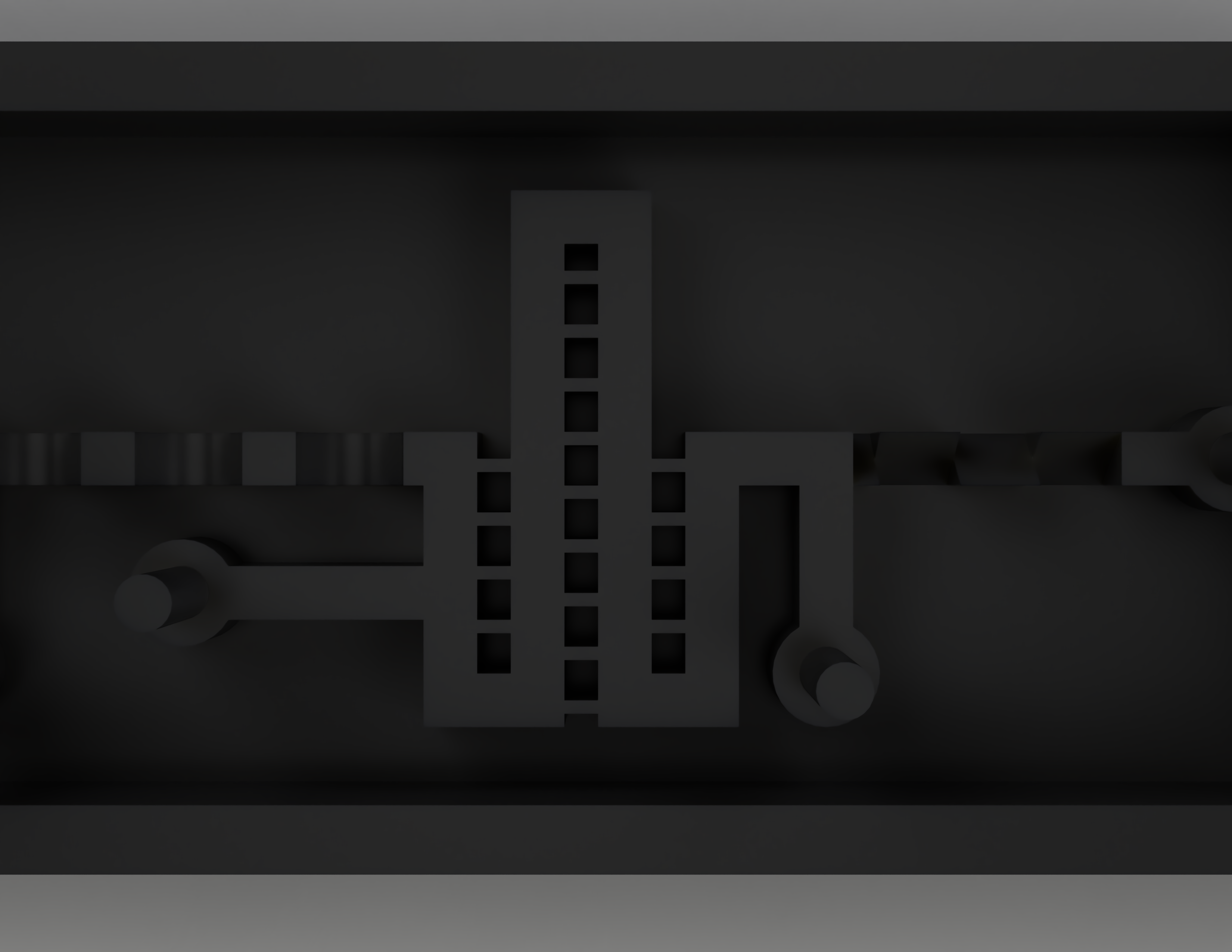
- Intersecting channels can be used to split, rearrange, and combine component streams to enhance mixing. The two species merge into a single large stream and flow along a main channel. The intersecting channels form connections between the parallel segments of the main channel, allowing fluid on one side of the main channel to interact with fluid on the other side of the channel.
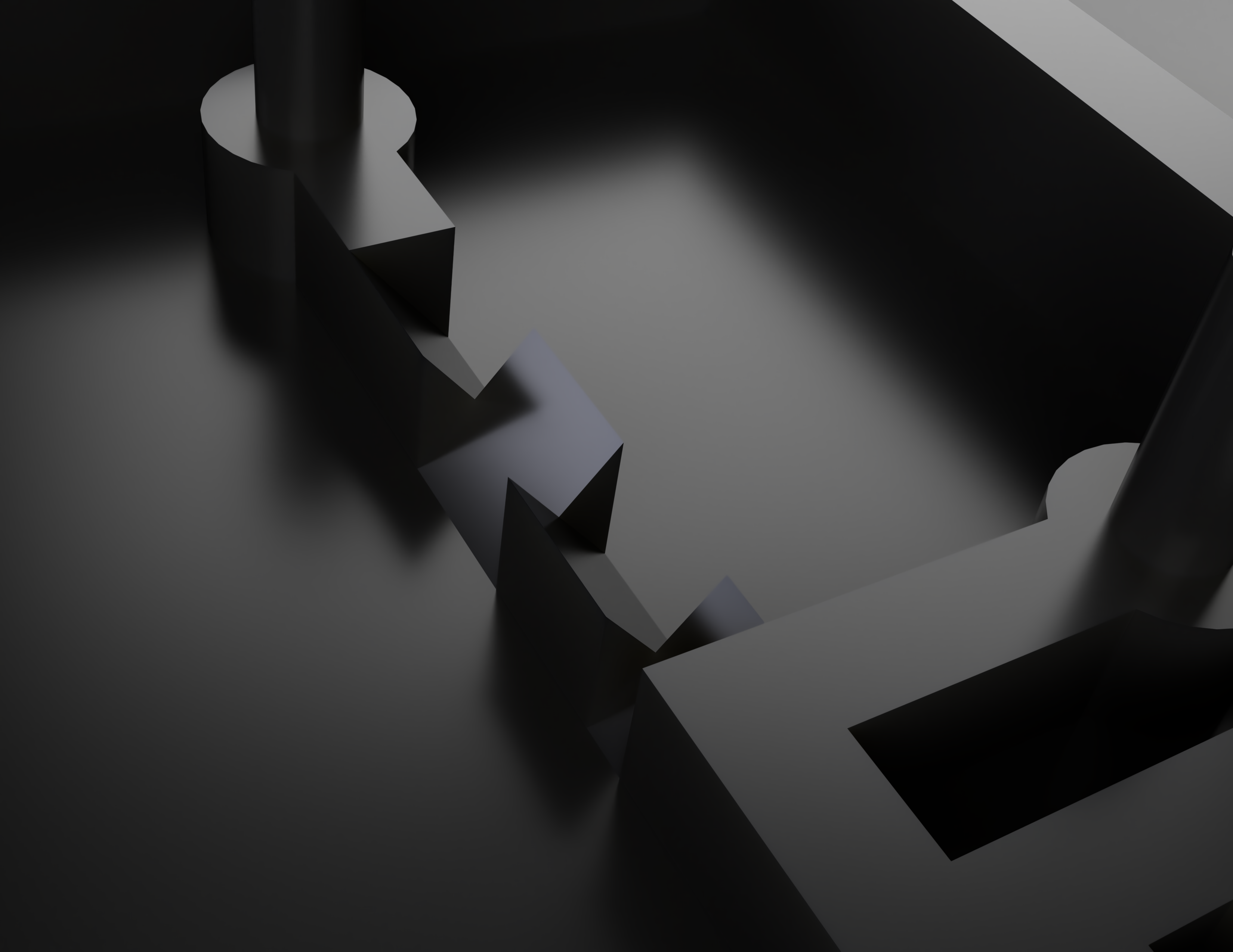
- Similar to the 3D ridges, the inclined walls in section 4 are designed to induce a chaotic mixing effect within the fluid stream. As the fluid traverses this section, it sways from side to side, resulting in a chaotic advection effect.
- Pertinent dimensions of the design include:
- Total length: 80.00 mm
- Total width: 30.00 mm
- Outer height: 5.50 mm
- Inner height: 4.50 mm
- Wall thickness: 2.50 mm
- Channel height: 2.50 mm
- Channel width: 2.00 mm
- Microfluidic connection post diameter: 2.00 mm
- Section length: 16.25 mm
Justification for Stereolithography
- SLA falls under the category of vat photopolymerization (VPP), which constructs a model layer by layer out of a vat of liquid photopolymer resin.
- An ultraviolet (UV) laser is used to cure the resin on each layer, and a platform moves the object being made downwards after each new layer is cured.
- VPP provides extremely high-resolution printing capabilities, with the minimum feature size being determined by the laser spot size (in this case, 85 um)
- Other fabrication techniques can also be used to create microfluidic devices, such as photolithography, a traditional technique that was first used to create microfluidic devices
- However, microfluidics fabricated with photolithography have a much higher cost and can also take much longer to fabricate
- Devices fabricated with photolithography can cost ~10x more than devices fabricated with SLA, largely due to the high maintenance costs of the equipment and facilities needed to run photolithography processes
- Ordering a microfluidic device fabricated with photolithography can also result in lead times of up to two months
- SLA parts can be ready in a matter of hours, allowing for rapid testing and prototpyping of microfluidic devices
- Traditional microfluidic devices made with photolithography are limited to a two-dimensional plane and a rectangular cross-sectional area
- SLA-printed microfluidics are limited only by what the user models in CAD, allowing for channels to take any three-dimensional path
- This is particularly beneficial for a homogeneous mixer, necessitating the use of SLA printing
- However, microfluidics fabricated with photolithography have a much higher cost and can also take much longer to fabricate
Video
CAD Model
References
“Guide to Microfluidics and Millifluidics, and Lab-on-a-Chip Manufacturing.” Formlabs, https://formlabs.com/blog/microfluidics-millifluidics-lab-on-a-chip-manufacturing/. Accessed 29 March 2023.
Hung, Chia -, et al. “Experimental Study on Microfluidic Mixing with Different Zigzag Angles.” NCBI, 31 August 2019, https://www.ncbi.nlm.nih.gov/pmc/articles/PMC6780503/. Accessed 29 March 2023.
“Microfluidic Mixing: A Review - PMC.” NCBI, 18 May 2011, https://www.ncbi.nlm.nih.gov/pmc/articles/PMC3116190/. Accessed 29 March 2023.
“An overview of microfluidic mixing application.” DORAS, https://doras.dcu.ie/20464/1/_Naher_AMR_2010_Overview_of_microfluidic_mixing.pdf. Accessed 29 March 2023.
Ward, Kevin. “Mixing in microfluidic devices and enhancement methods.” NCBI, https://www.ncbi.nlm.nih.gov/pmc/articles/PMC4634658/. Accessed 29 March 2023.
Team
Andy Du, Vanderbilt School of Engineering, Mechanical Engineering
Kaelon McNeece, Vanderbilt School of Engineering, Mechanical Engineering