BikeLight
Spring 2022
ME 3204 Mechatronics
Problem
- Biking at night can be dangerous since it is difficult for pedestrians and motorists to see when bicyclists are signaling for turns.
- As someone who lived off-campus and had to regularly bike home at night after long days on campus, this was a problem I faced regularly.
Solution
- The solution I developed was the BikeLight: an automated LED signaling system for bikers that includes a hand-mounted turn signal component and a brake light component on the rear of the bike.
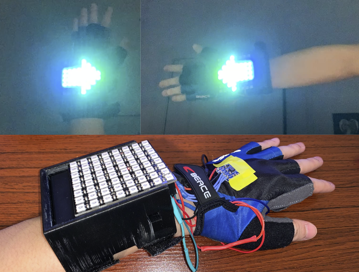
- For the hand-mounted component, an accelerometer senses the position of the bicyclist’s hand and the BikeLight displays an arrow in the direction the bike is going to turn based on traditional turning hand signals.
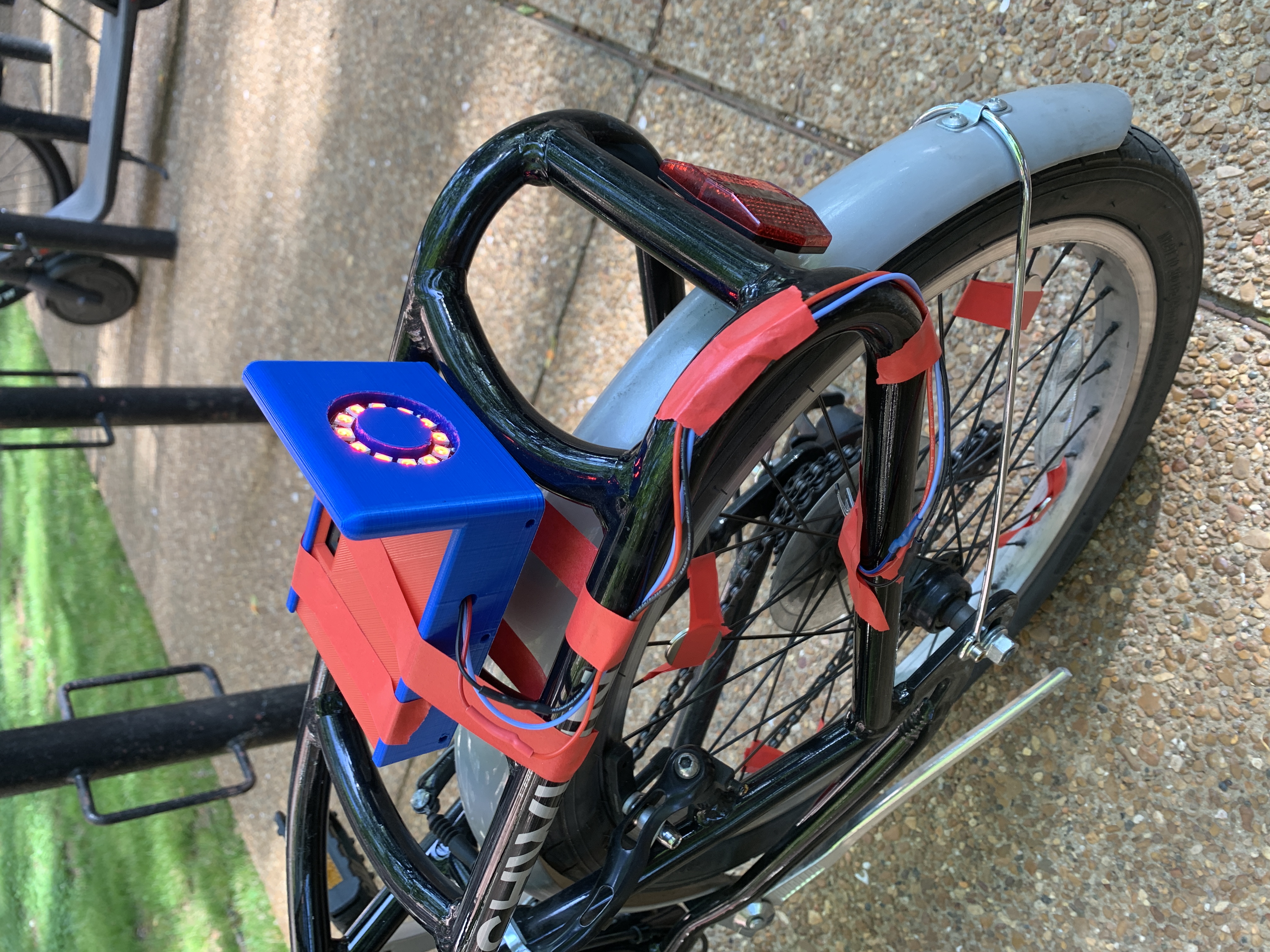
- For the rear bike-mounted component, the rear brake light blinks when the bicycle is slowing down and emits light continuously when the bike is fully stopped.
Video
System Components, Integration, and Construction
Hand-Mounted Turn Signal
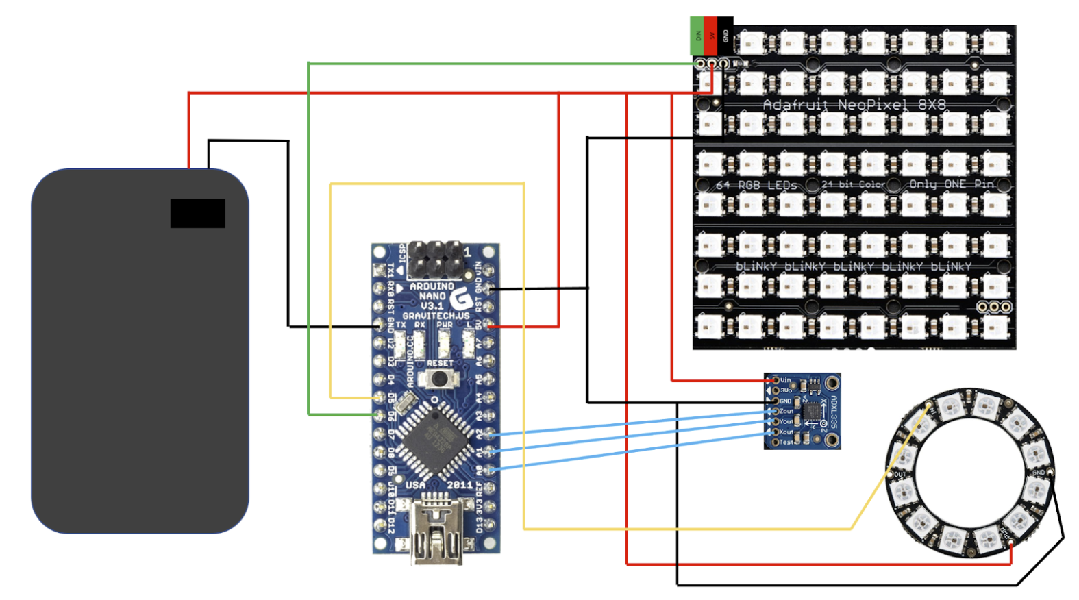
- The sensor for the hand-mounted component was an ADXL335 3-axis accelerometer mounted to the back of the hand.
- This accelerometer reads hand position based on 3 analog values sent to the microcontroller in the form of x, y, and z acceleration values.
- Based on these 3 signals, thresholds were set that correspond to various hand positions.
- As seen below in Figure 1, for each hand position, one accelerometer signal was on one side of the threshold while the other two signals were on the opposite side.
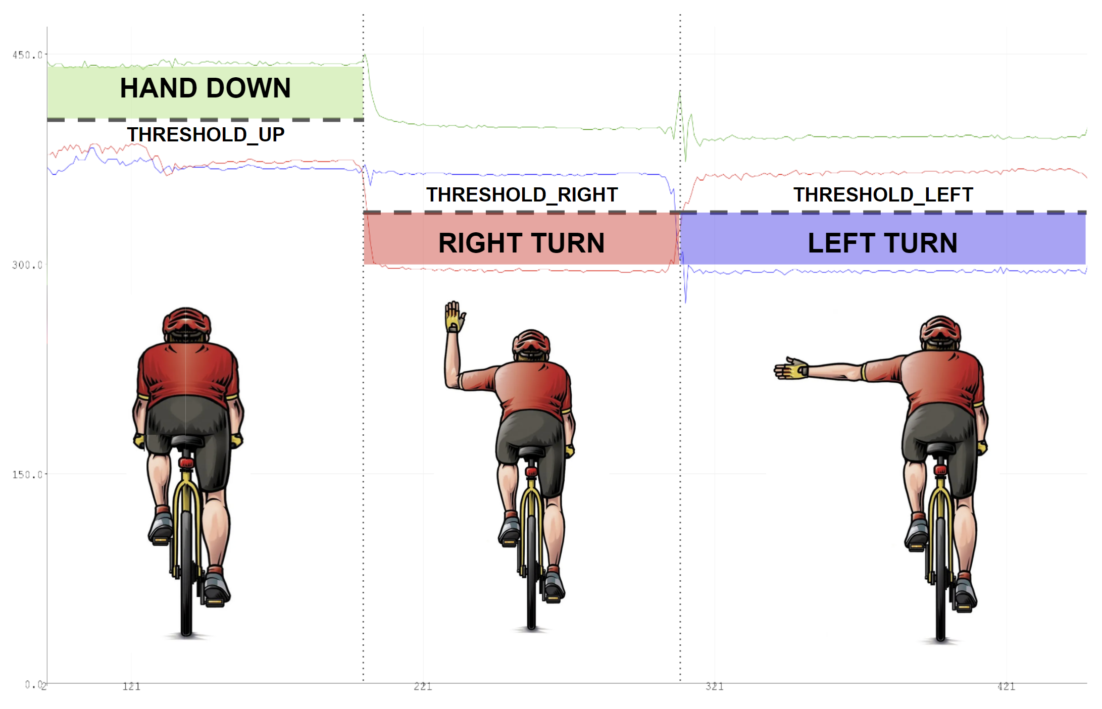 Figure 1. Serial plot of accelerometer signals with threshold values and hand signals visualized.
- Once the exact hand position was determined with the thresholds and accelerometer signals, the LED matrix and ring outputs were then animated.
- An Adafruit NeoPixel NeoMatrix and Ring were used, both of which are compatible with the Adafruit_NeoPixel.h Arduino library.
- The Arduino called a function that corresponded to the hand position case (leftArrow() or rightArrow()), and the LEDs were animated in the correct arrangement, seen below in Figure 2.
- The LED matrix provided signals for drivers and pedestrians located behind the bike, while the ring light rested on the biker’s palm and signaled the biker’s intentions to oncoming traffic.
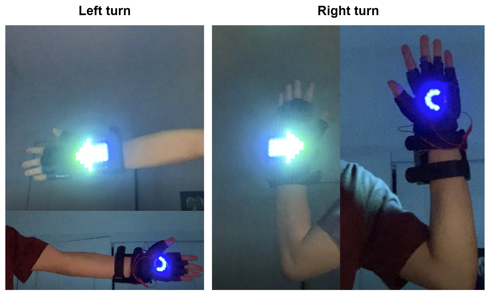 Figure 2. LED matrix and ring in the left and right turn hand positions, visible to both rear and oncoming traffic.
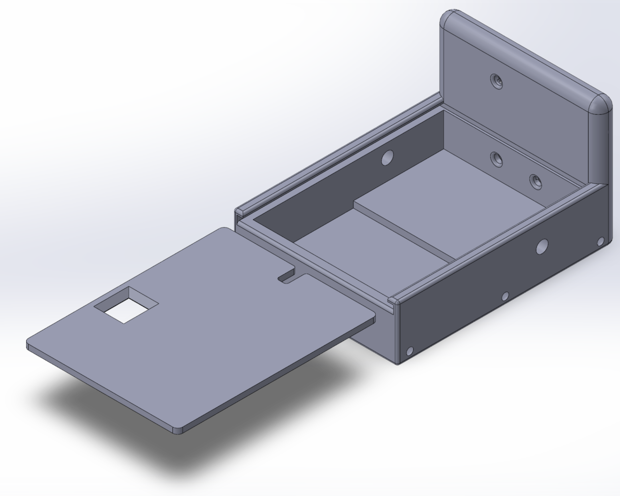
- A wrist-mounted case was modeled using SOLIDWORKS and 3D printed with Velcro straps securing it to the arm.
- A battery pack that held three 1.5V AA batteries supplied 4.5V to the LED panels and Arduino Nano microcontroller.
- The proper connections were soldered together and any exposed wirings were covered with heat shrink wire casing to create the final product, seen below in Figure 3.
- The entire system can be turned on and off using the battery pack switch and does not hinder the biker’s grip on the handlebars.
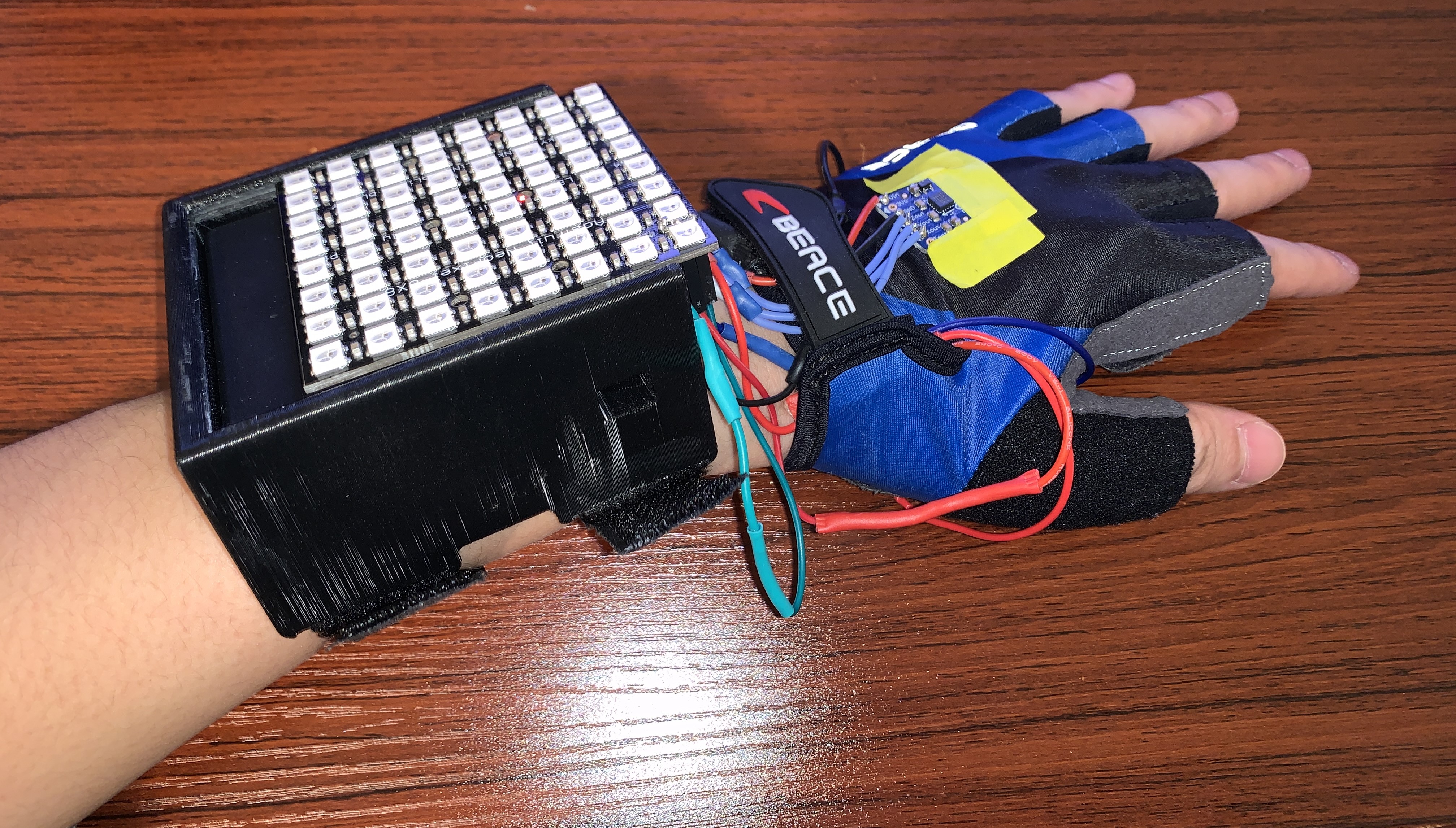
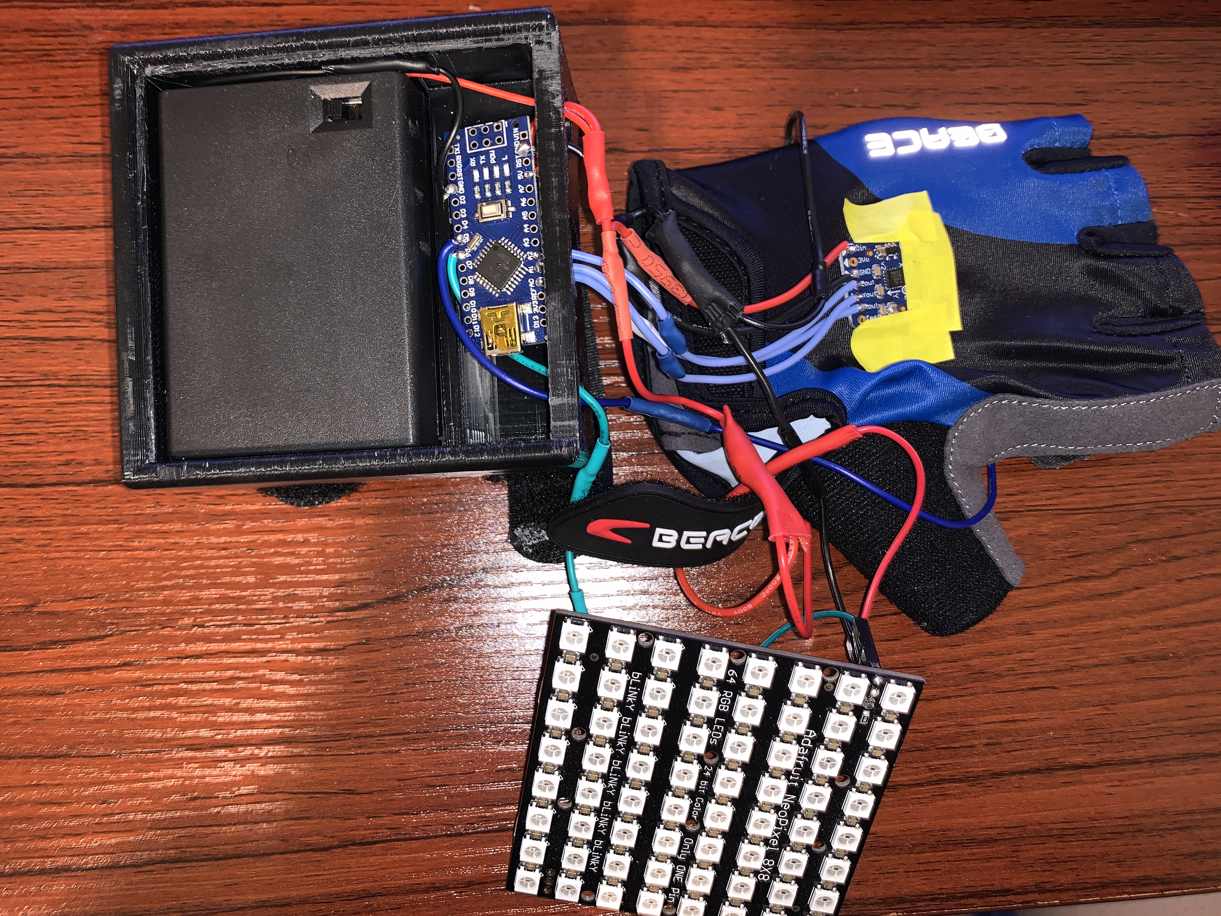
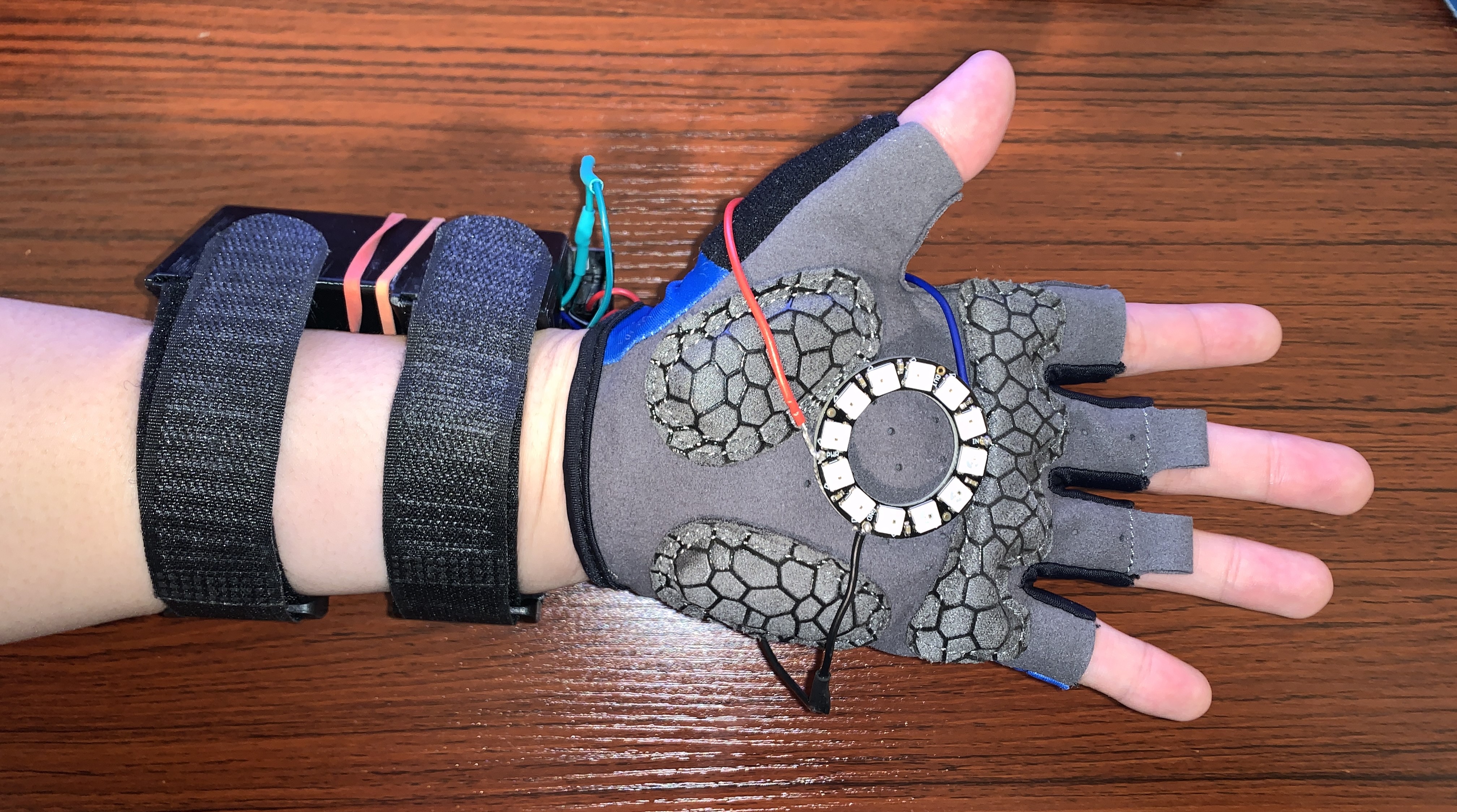
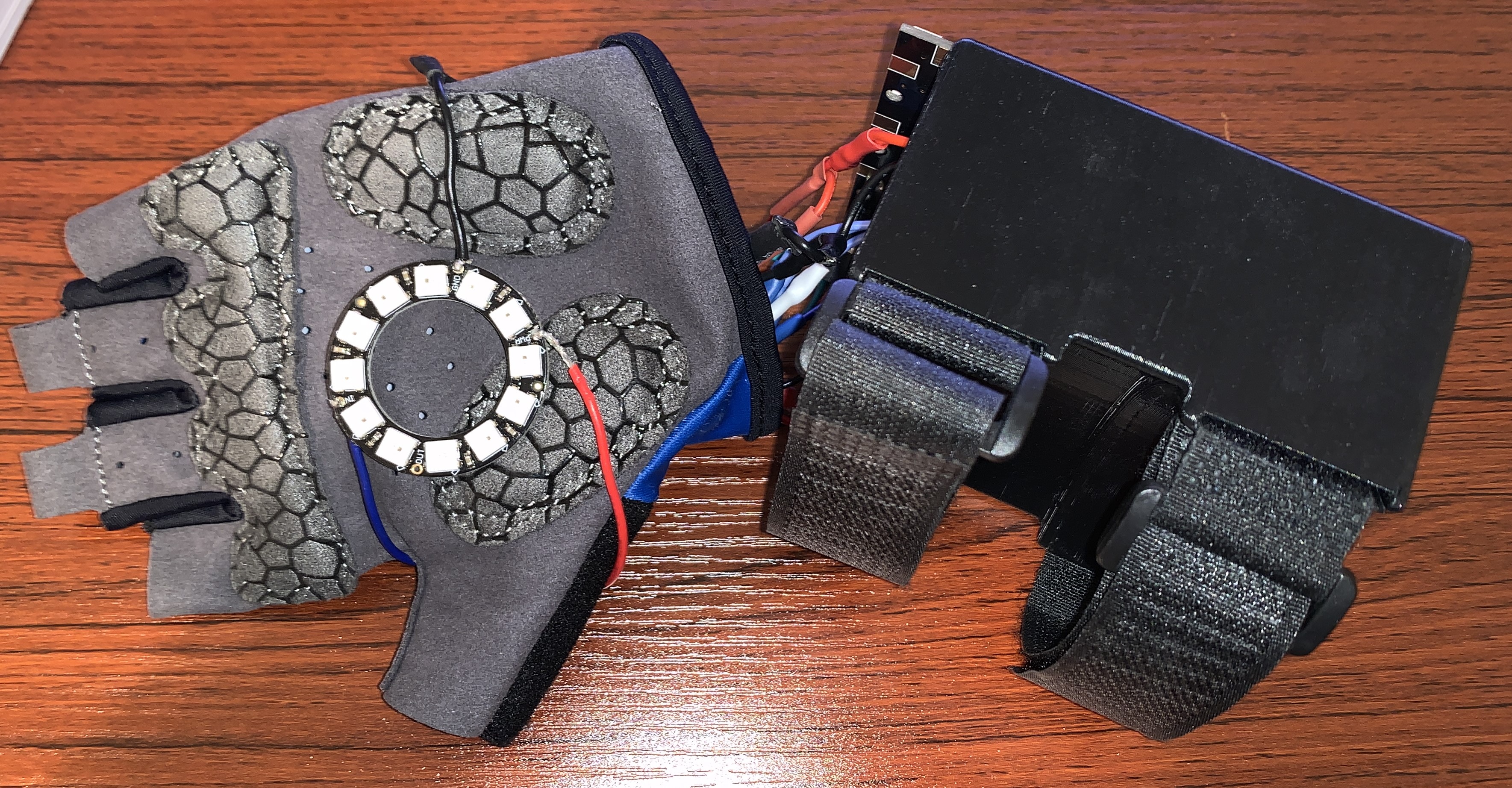 Figure 3. Final hand-mounted turn signal component including 3D-printed case
Rear Brake Light
- Four neodymium magnets were taped onto the rear wheel spokes equidistant from each other.
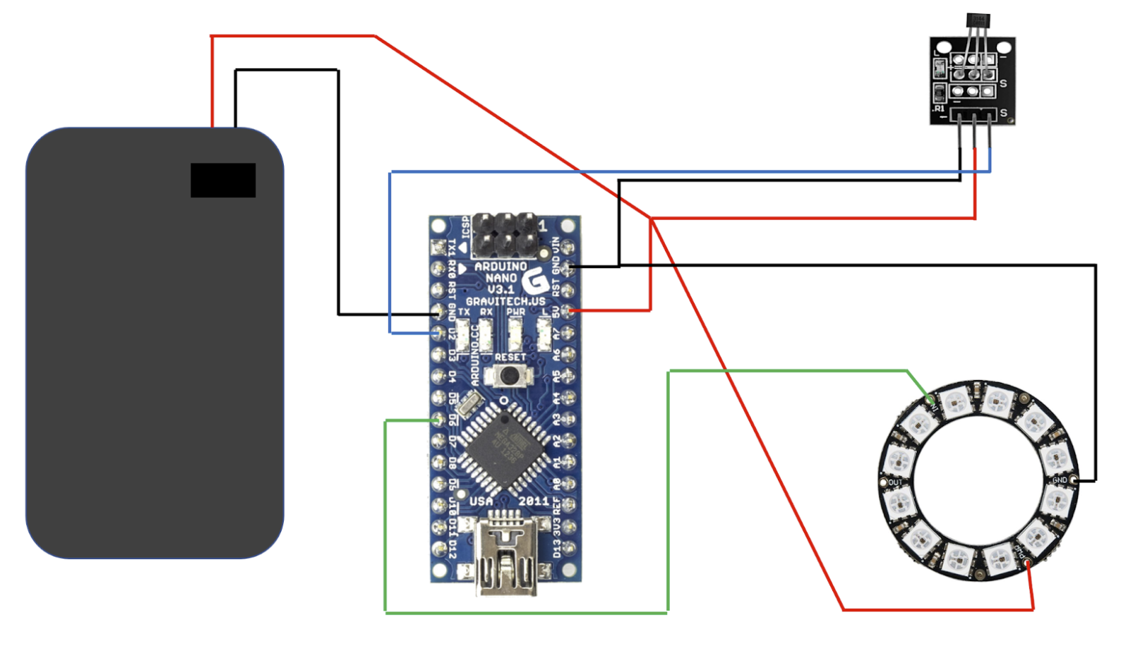
- A Hall effect sensor was attached to the bike frame so that as the wheel spins, the sensor is able to detect the four magnets.
- Each time a magnet is detected by the Hall sensor, an ISR is triggered in digital pin 2 of the Arduino such that a counter is incremented every time a magnet is detected. Over a sampling period of 1 second, a wheel speed is calculated by dividing the number of counts by the sampling time.
- Each speed is compared to the previous wheel speed to determine if the bike is slowing down.
- If the bike is slowing down, the ring LED will trigger a built-in animation to indicate deceleration.
- Once the bike completely stops, the ring LED will display a solid red light.
- Like the hand-mounted turn signal, the rear brake light is also controlled by an Arduino Nano and powered by 3 AA batteries that supply 4.5 V to the Nano and NeoPixel ring LED.
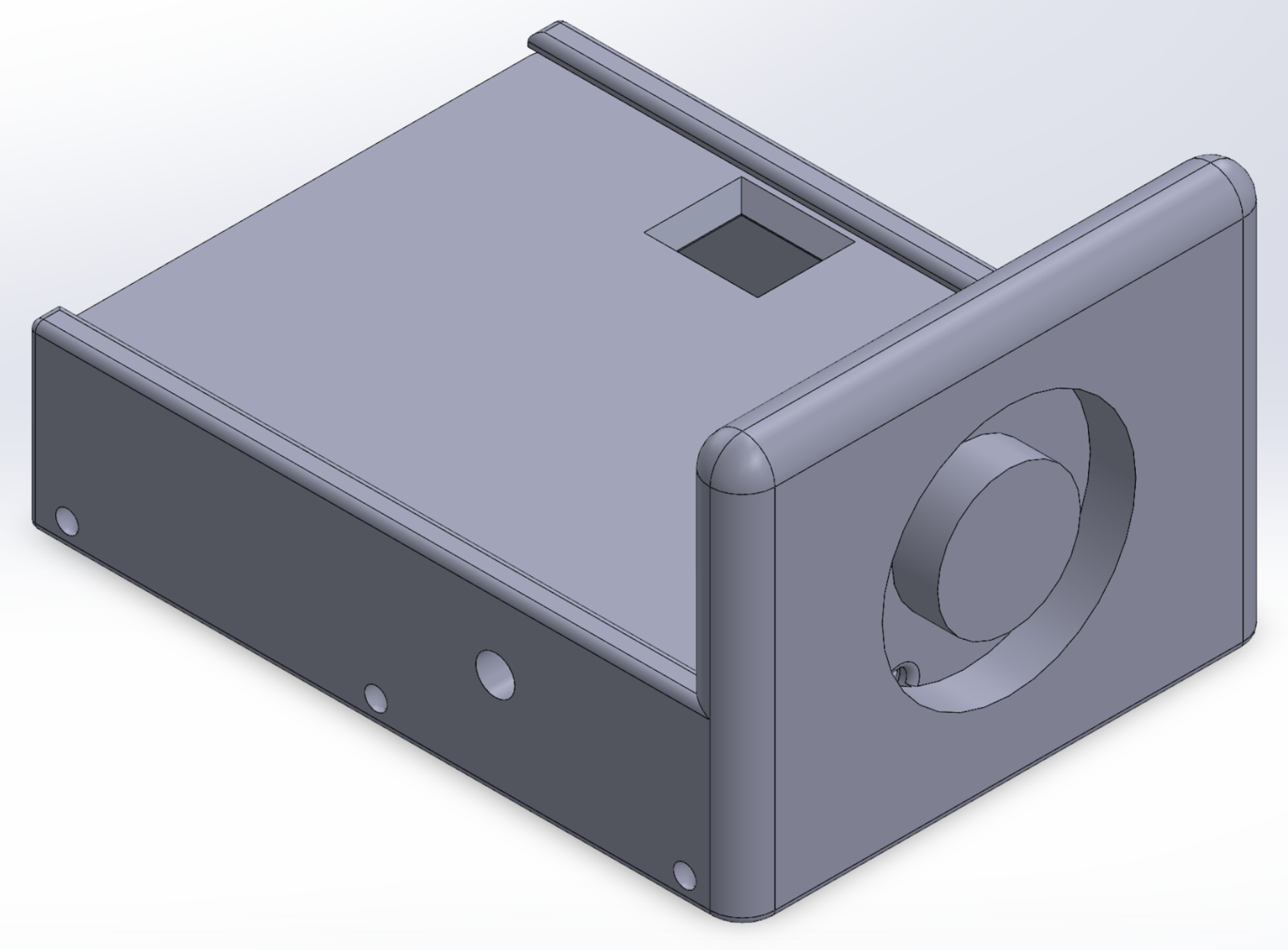
- The ring LED is mounted to the case and the Hall effect sensor is wired from the Nano to the bike frame, seen below in Figure 4.
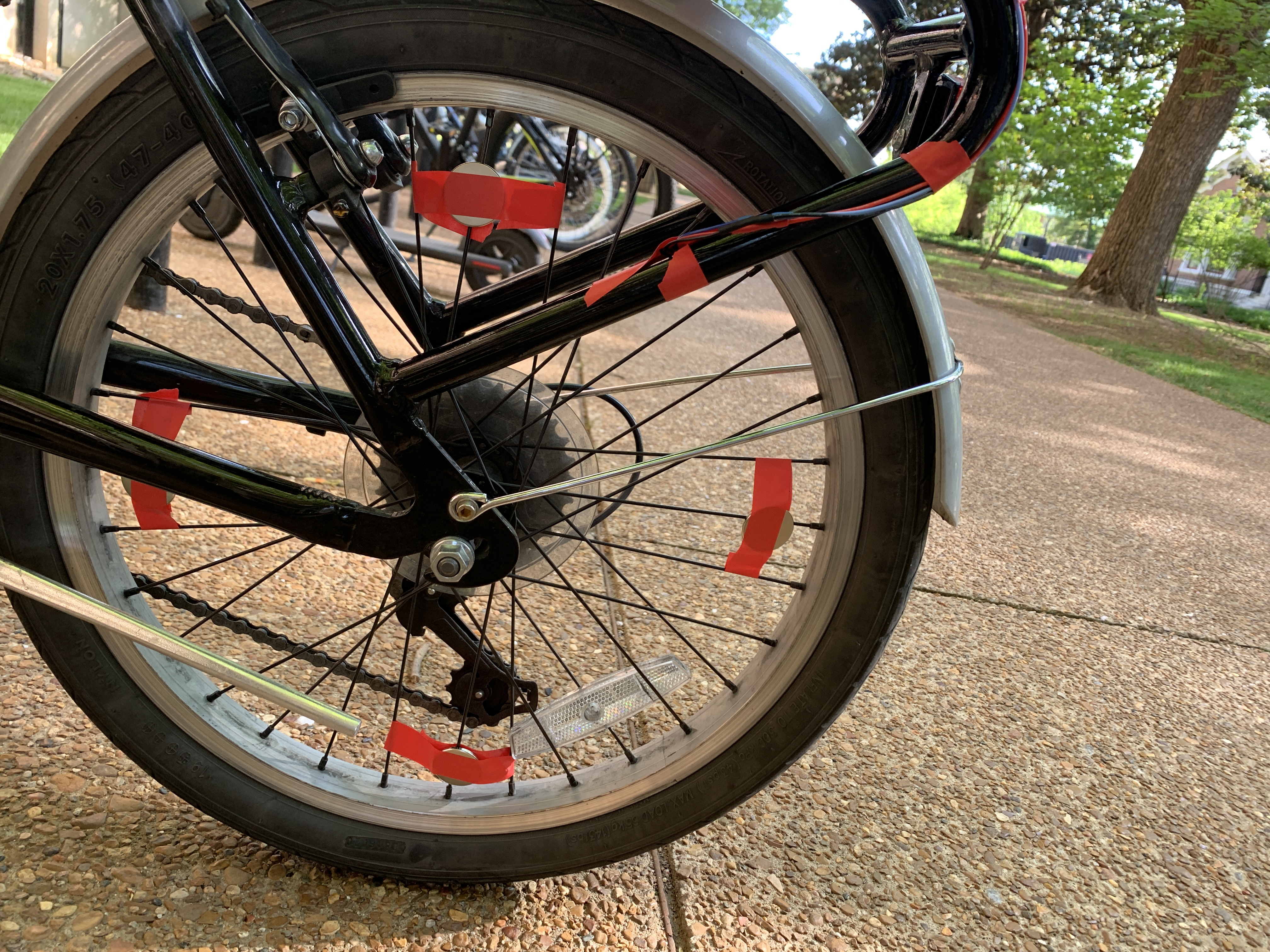
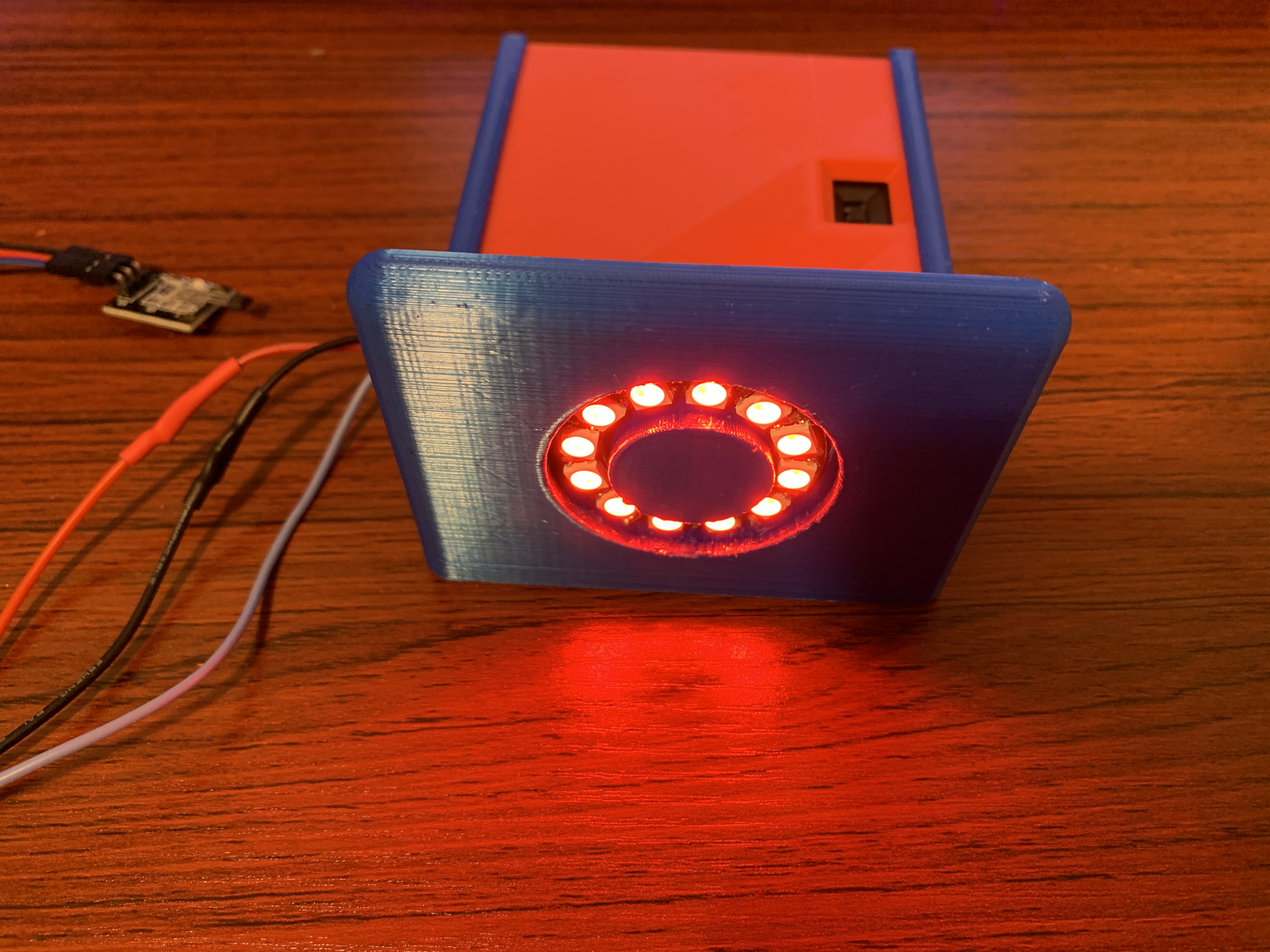
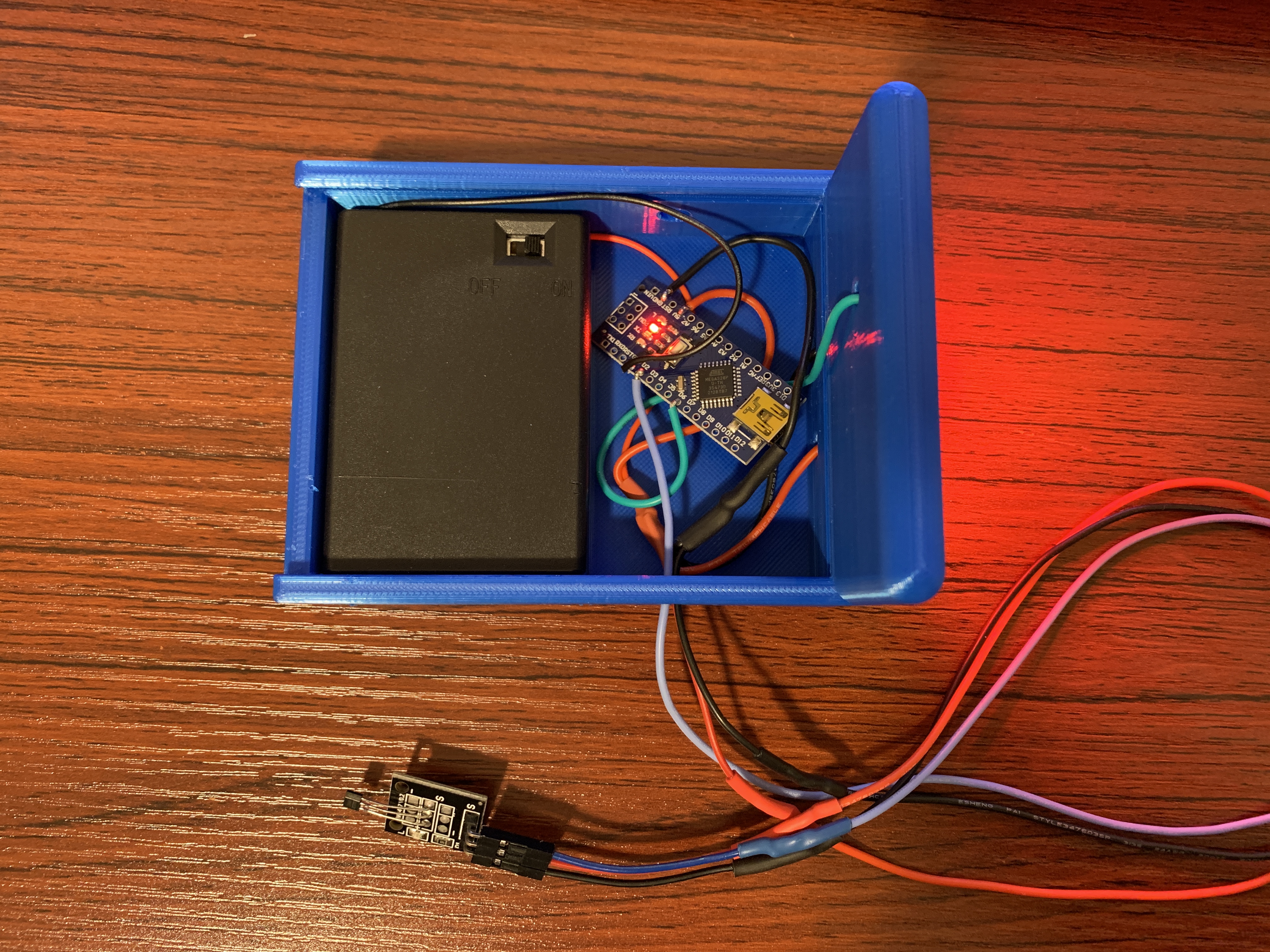
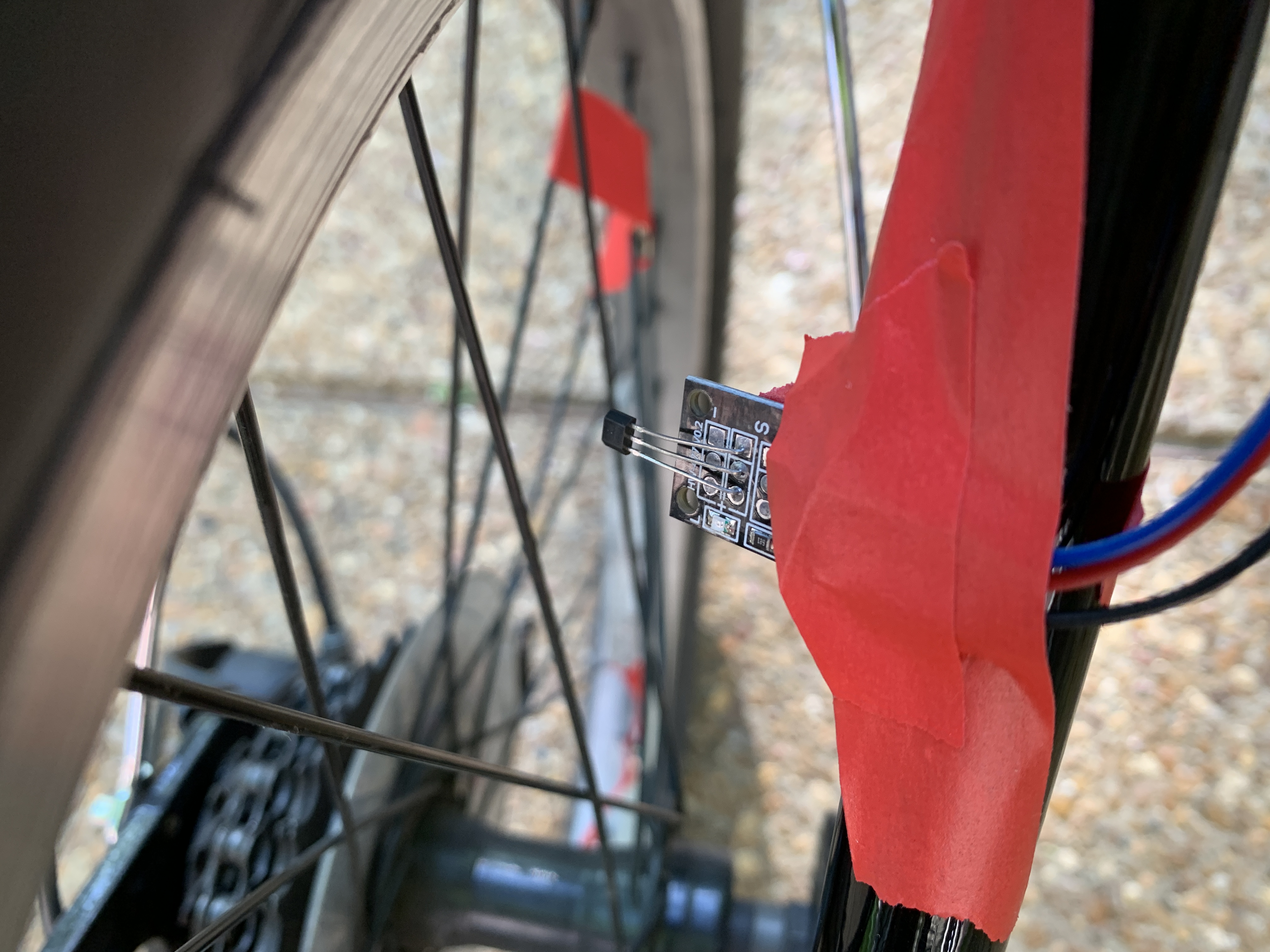 Figure 4. Rear brake system with four neodymium magnets taped on the rear wheel spokes and a Hall sensor wired to the Arduino Nano.
CAD
Hand-Mounted Turn Signal Case
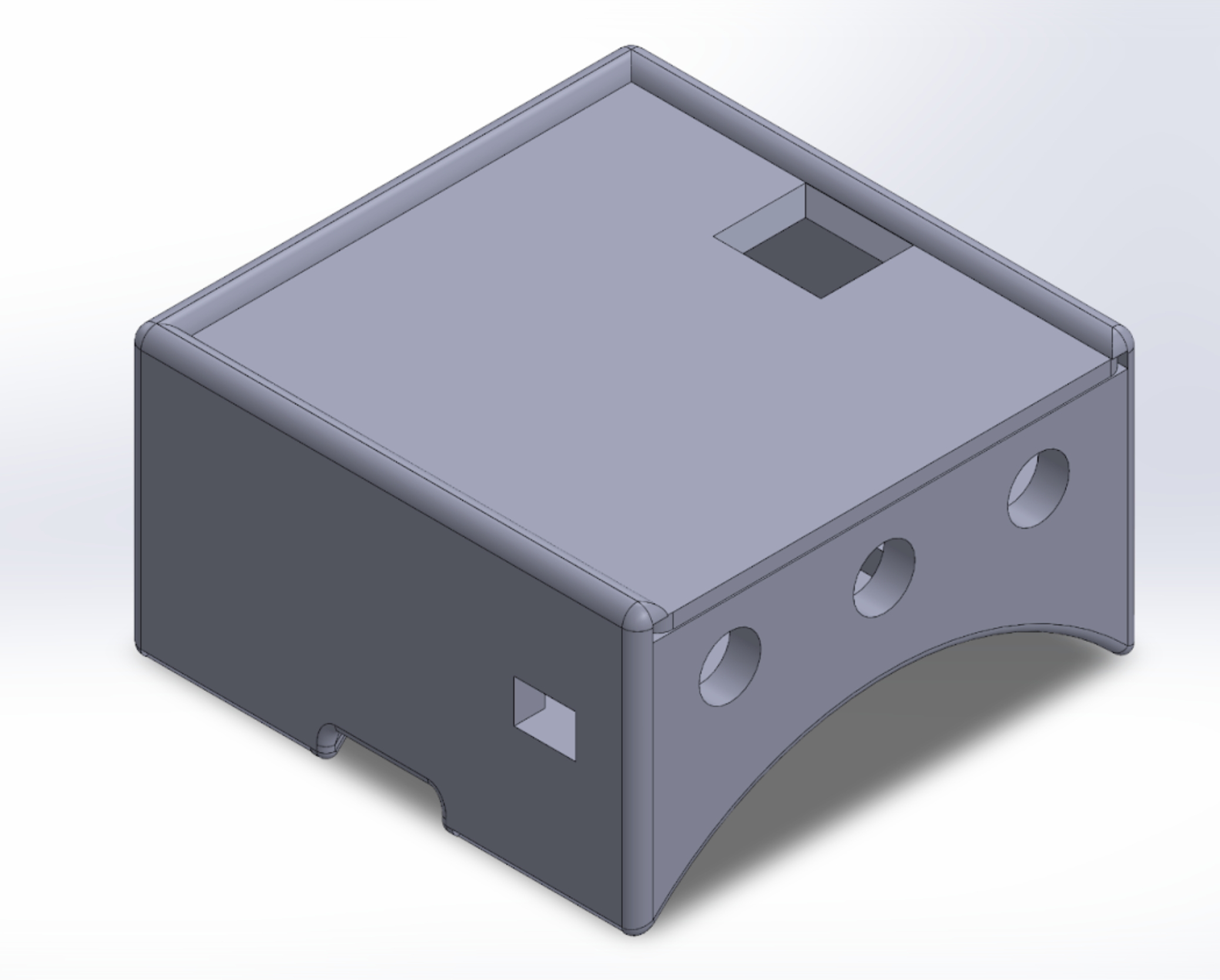
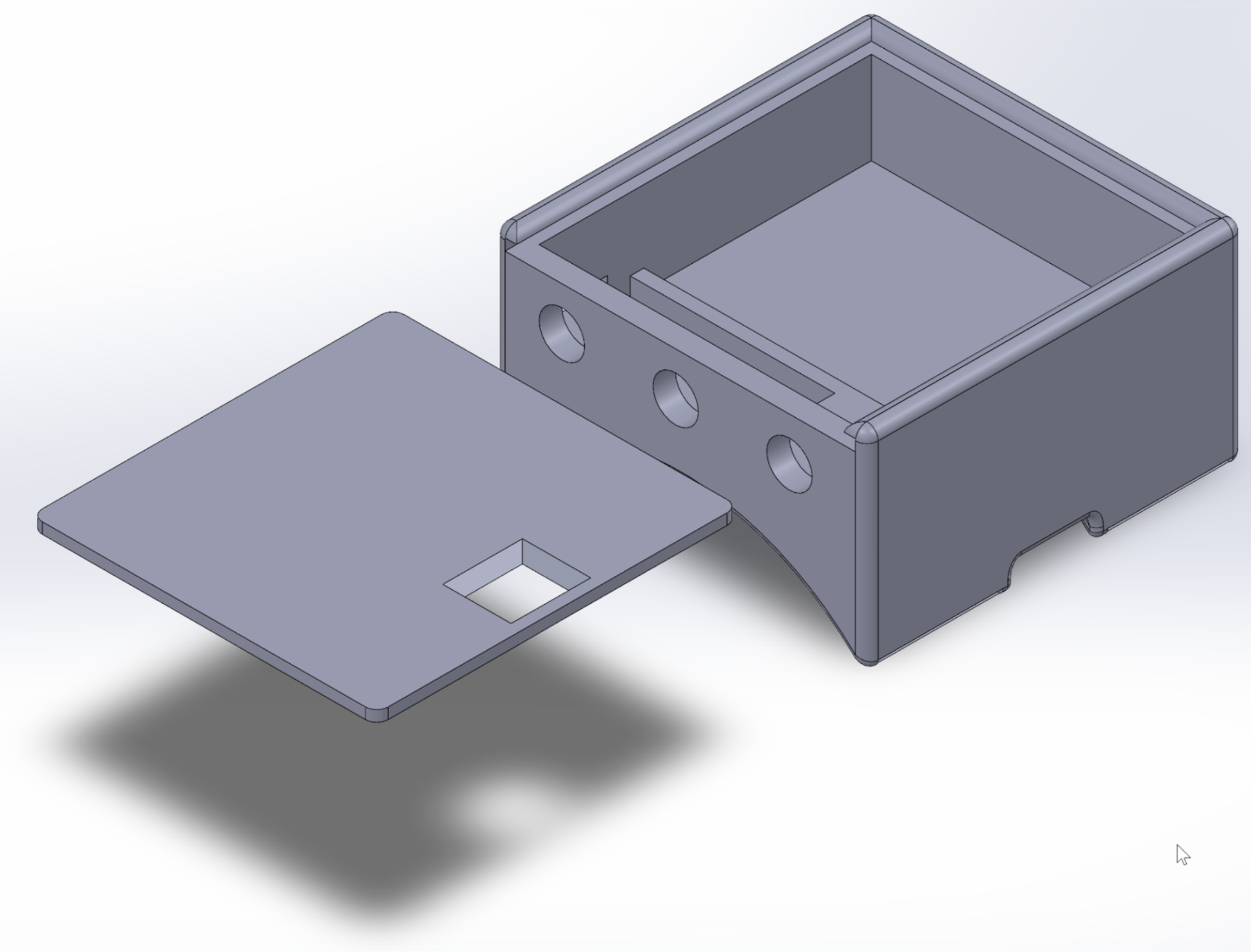
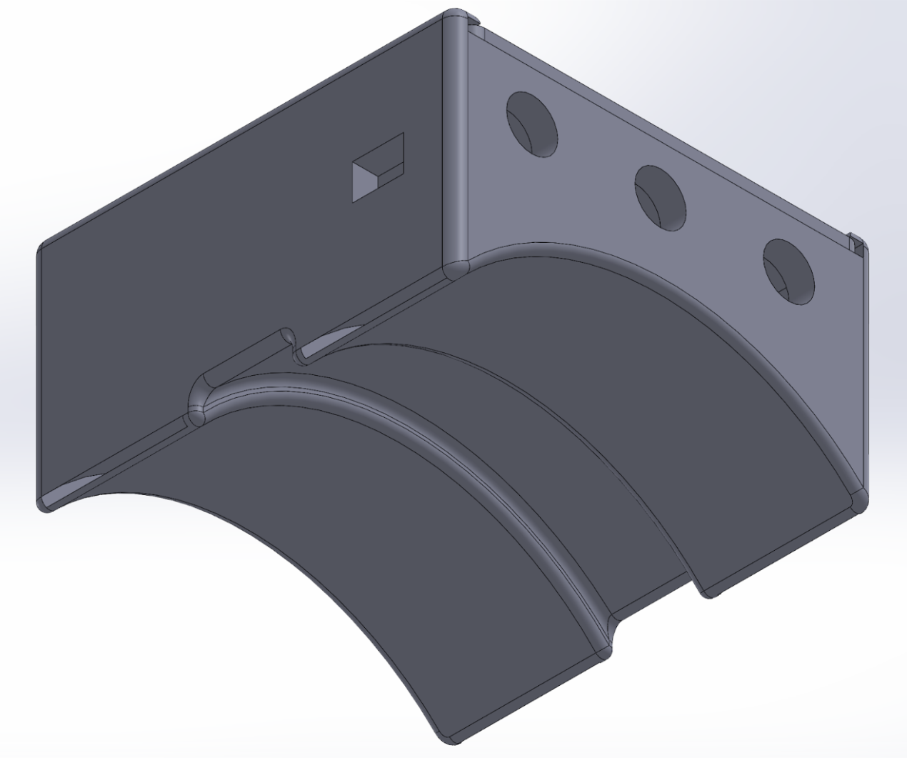
Rear Brake Signal Case
Circuit Schematics
Hand-Mounted Turn Signal
Rear Brake Signal
Materials
Hand-Mounted Turn Signal
| Component | Quantity |
|---|---|
| ADXL335 triple-axis accelerometer | 1 |
| Adafruit NeoPixel NeoMatrix 8x8 - 64 RGB LED Pixel Matrix | 1 |
| Adafruit NeoPixel Ring - 12 x 5050 RGB LED | 1 |
| 1”x12” Velcro Reusable Cinch Straps | 2 |
| 3x 1.5V AA Battery Holder with Leads and Switch | 1 |
| Arduino Nano | 1 |
| Cycling Gloves | 1 |
| 3D printed wrist mounting case | 1 |
| Wire, heat shrink tubing, solder | - |
Rear Brake Signal
| Component | Quantity |
|---|---|
| KY003 Magnetic Hall Effect Sensor | 1 |
| Adafruit NeoPixel Ring - 12 x 5050 RGB LED | 1 |
| 3x 1.5V AA Battery Holder with Leads and Switch | 1 |
| Arduino Nano | 1 |
| 3D printed wrist mounting case | 1 |
| Wire, heat shrink tubing, solder | - |
Code
Hand-Mounted Component
#include <Adafruit_GFX.h>
#include <Adafruit_NeoMatrix.h>
#include <Adafruit_NeoPixel.h>

// ACCELEROMETER STUFF
// Define accelerometer x,y,z pins
const int xpin = A0;
const int ypin = A1;
const int zpin = A2;

// Define Thresholds
#define THRESHOLD_UP      375  // threshold for default hand position
#define THRESHOLD_LEFT    325  // threshold for left turn hand position
#define THRESHOLD_RIGHT   325  // threshold for right turn hand position

// Define Matrix and Ring Pins
#define MATRIXPIN 6
#define RINGPIN 5

// Declare LED matrix
  // coordinate system starts on top left
  // row major progressive system
  // GRB coloring + correct frequency for board
Adafruit_NeoMatrix matrix = Adafruit_NeoMatrix(8, 8, MATRIXPIN,
  NEO_MATRIX_TOP     + NEO_MATRIX_LEFT +
  NEO_MATRIX_ROWS + NEO_MATRIX_PROGRESSIVE,
  NEO_GRB            + NEO_KHZ800);

// Declare LED ring
Adafruit_NeoPixel strip = Adafruit_NeoPixel(12, RINGPIN, NEO_GRB + NEO_KHZ800);

// Initialize basic RGB color values
uint32_t red = strip.Color(255,0,0);
uint32_t green = strip.Color(0,255,0);
uint32_t blue = strip.Color(0,0,255);

/***SETUP***/
void setup() {
  // Initialize serial communications
  Serial.begin(9600);

  // Start NeoMatrix
  matrix.begin();
  matrix.setBrightness(100);
  matrix.show(); // Initialize all pixels to 'off'

  // Start NeoPixel ring
  strip.begin();
  strip.setBrightness(100);
  strip.show(); // Initialize all pixels to 'off'
} // end setup

/***LOOP***/
void loop() {

  // Read accelerometer values
  int xval = analogRead(xpin);
  int yval = analogRead(ypin);
  int zval = analogRead(zpin);

  // Determine hand position
  if (zval>THRESHOLD_UP & xval<THRESHOLD_UP & yval<THRESHOLD_UP){
    Serial.println("HAND DOWN");
    matrix.clear();
    matrix.show();
    strip.clear();
    strip.show();
  } // end if

  else if (zval>THRESHOLD_LEFT & xval<THRESHOLD_LEFT & yval>THRESHOLD_LEFT){
    Serial.println("LEFT TURN");
    leftArrow();
  } // end else if

  else if (zval>THRESHOLD_RIGHT & xval>THRESHOLD_RIGHT & yval<THRESHOLD_RIGHT){
    Serial.println("RIGHT TURN");
    rightArrow();
  } // end else if

  else {
    matrix.clear();
    matrix.show();
    strip.clear();
    strip.show();
  } // end else

  /*
  // Debug Accelerometer/Print the sensor values:
    Serial.print(analogRead(xpin));
    Serial.print("\t");
    Serial.print(analogRead(ypin));
    Serial.print("\t");
    Serial.print(analogRead(zpin));
    Serial.println();
    delay(100);
  */

  /*
  // Debug Matrix/rightArrow and leftArrow functions:
    rightArrow();
    delay(2000);
    matrix.clear();
    matrix.show();
    delay(1000);

    leftArrow();
    delay(2000);
    matrix.clear();
    matrix.show();
    delay(1000);
  */

} // end loop

// Function to display left turn arrow
void leftArrow(){

  // Matrix
  matrix.clear();
  for (int i=23; i<=47; i=i+8){
    matrix.setPixelColor(i,strip.Color(0,50,255));
  } // end for
  matrix.show();
  delay(25);

  for (int i=22; i<=46; i=i+8){
    matrix.setPixelColor(i,strip.Color(0,100,255));
  } // end for
  matrix.show();
  delay(25);

  for (int i=21; i<=45; i=i+8){
    matrix.setPixelColor(i,strip.Color(0,150,255));
  } // end for
  matrix.show();
  delay(25);

  for (int i=20; i<=45; i=i+8){
    matrix.setPixelColor(i,strip.Color(0,255,255));
  } // end for
  matrix.show();
  delay(25);

  for (int i=3; i<=59; i=i+8){
    matrix.setPixelColor(i,strip.Color(0,255,150));
  } // end for
  matrix.show();
  delay(25);

  for (int i=10; i<=50; i=i+8){
    matrix.setPixelColor(i,strip.Color(0,255,100));
  } // end for
  matrix.show();
  delay(25);

  for (int i=17; i<=41; i=i+8){
    matrix.setPixelColor(i,strip.Color(0,255,50));
  } // end for
  matrix.show();
  delay(25);

  for (int i=24; i<=32; i=i+8){
    matrix.setPixelColor(i,strip.Color(0,255,25));
  } // end for
  matrix.show();
  delay(75);

  // Ring
  strip.setPixelColor(3,blue);
  strip.setPixelColor(9,blue);
  strip.show();
  delay(35);
  strip.setPixelColor(2,blue);
  strip.setPixelColor(10,blue);
  strip.show();
  delay(35);
  strip.setPixelColor(1,blue);
  strip.setPixelColor(11,blue);
  strip.show();
  delay(35);
  strip.setPixelColor(0,blue);
  strip.show();
  delay(125);
  strip.clear();
  strip.show();
} // end leftArrow

// Function to display right turn arrow
void rightArrow(){
   // Matrix
  matrix.clear();
  matrix.fill(strip.Color(0,50,255),58,4);
  matrix.show();
  delay(25);

  matrix.fill(strip.Color(0,100,255),50,4);
  matrix.show();
  delay(25);

  matrix.fill(strip.Color(0,150,255),42,4);
  matrix.show();
  delay(25);

  matrix.fill(strip.Color(0,255,255),34,4);
  matrix.show();
  delay(25);

  matrix.fill(strip.Color(0,255,150),24,8);
  matrix.show();
  delay(25);

  matrix.fill(strip.Color(0,255,100),17,6);
  matrix.show();
  delay(25);

  matrix.fill(strip.Color(0,255,50),10,4);
  matrix.show();
  delay(25);

  matrix.fill(strip.Color(0,255,25),3,2);
  matrix.show();
  delay(75);

  // Ring
  strip.setPixelColor(0,blue);
  strip.setPixelColor(6,blue);
  strip.show();
  delay(35);
  strip.setPixelColor(11,blue);
  strip.setPixelColor(7,blue);
  strip.show();
  delay(35);
  strip.setPixelColor(10,blue);
  strip.setPixelColor(8,blue);
  strip.show();
  delay(35);
  strip.setPixelColor(9,blue);
  strip.show();
  delay(125);
  strip.clear();
  strip.show();
} // end rightArrow
Brake Component
#include <Adafruit_NeoPixel.h>

 // Define Ring Pin
 #define RINGPIN 6

 // Declare LED ring
    // 12 LEDs on ring
    // Input pin number
    // GRB coloring + correct frequency for board
 Adafruit_NeoPixel strip = Adafruit_NeoPixel(12, RINGPIN, NEO_GRB + NEO_KHZ800);

 // Define 'red' color in RGB values
 uint64_t red = strip.Color(255,0,0);

 // Initialize speed counter variables
 int rev_count = 0;
 const float sample_period = 1; // sampling period in sec
 long timer1 = millis();
 float rps;
 float oldrps;

 /***SETUP***/
 void setup(){
   // Initialize serial communications
   Serial.begin(115200);

   // Start NeoPixel ring
   // Initialize all pixels to 'off'
   strip.begin();
   strip.setBrightness(100);
   strip.show();

   // Magnet interrupt stuff
   // Initialize the interrupt pin (Arduino digital pin 2)
   attachInterrupt(0, magnet_detect, RISING);
   rev_count = 0;
   rps = 0;
   oldrps=rps;

 } // end setup

 /***LOOP***/
 void loop(){

   // Clear ring
   strip.clear();
   strip.show();


   // If enough time has passed (enough samples to take rev/sec)
   if (millis() - timer1 > (1000 * sample_period)) {
     rps=(1000*rev_count)/(millis()-timer1); // find rev/sec
     rev_count = 0; // reset rev_count for next cycle
     timer1 = millis(); // start time for next cycle

     Serial.println(rps); // print rev/sec for debugging

     // See if the wheel is slowing down
     if (rps<oldrps){
      //Serial.println("Slowing down");
       theaterChase(red,50);

     } //  end slow down if
   } // end sampling if

   // If the bike isn't moving
   if (rps==0){
    strip.fill(red,0,64); // Fill with solid red
    strip.show();
   } // end if


    // Update rpm value
    oldrps=rps;

 } // end loop

 // Called whenever a magnet is detected
 void magnet_detect(){
    rev_count++;
 } // end magnet_detect()


 // Theatre-style crawling lights (from NeoPixel example code)
  void theaterChase(uint32_t c, uint8_t wait) {
    for (int j=0; j<7; j++) {  //do 10 cycles of chasing
      for (int q=0; q < 3; q++) {
        for (uint16_t i=0; i < strip.numPixels(); i=i+3) {
          strip.setPixelColor(i+q, c);    //turn every third pixel on
        } // end for
        strip.show();

        delay(wait);

        for (uint16_t i=0; i < strip.numPixels(); i=i+3) {
          strip.setPixelColor(i+q, 0);        //turn every third pixel off
        } // end for
      } // end for
    } // end for
  } // end theaterChase